CUBIC6 IP1812 - rev. 2008-08-25 I GB F D E P DITEC S.p.A. Via Mons. Banfi, 3 - 21042 Caronno Pertusella (VA) - ITALY Tel. +39 02 963911 - Fax +39 02 9650314 www.ditec.it - ditec@ditecva.com Manuale di installazione e manutenzione per automazioni per cancelli a battente. Installation and maintenance manual for automations for swing gates. Manuel d’installation et d’entretien pour portes à battant. Montage und Wartungshandbuch für automatisierte Drehtore.
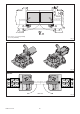
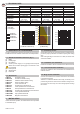
3 5 4x0.5 mm² 7 7 TX - 4x0.5 mm² RX - 4x0.5 mm² 6 * * 6 1 4 7 7 TX - 4x0.5 mm² 3x1.5 mm² 2x1.5 mm² RX - 4x0.5 mm² (*) 3x0,75 mm² + 1x1,5 mm² [CUBIC6] 2x1,5 mm² [CUBIC6H] Fig. 1 CUBIC6 CUBIC6H Fig. 2 CUBIC6L CUBIC6LG max 110° CUBIC6 - IP1812 2 Fig.
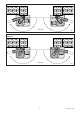
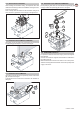
CUBIC6TC max 180° Fig. 4 CUBIC6TI CUBIC6TIG max 180° 3 Fig.
GENERAL SAFETY PRECAUTIONS - affix the CE mark on the motorised door pursuant to para. 1.7.3 of Schedule I of the Machine Directive. For more details, refer to the “Guidelines for producing technical documentation” available on Internet at the following address: www.ditec.it This installation manual is intended for professionally competent personnel only.
GB 1.
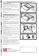
3.5 Geared motor installation 3.8 Installation with CUBIC6TI-CUBIC6TIG After installing the foundation casing, the respective lever and release mechanisms go before the installation of the gear motor as shown in the figure. Note: carefully clean the bottom of the foundation casing from dirt or cement to guarantee an even laying of the gearmotor. Fix the plate [A], then insert, fix and lubricate the gears [B], [C] and [D]. Position the sphere [E] as shown in the figure. D C B A E 3.
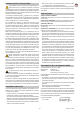
GB 4. ELECTRICAL CONNECTIONS Attention: the electrical connections for the extension of the motor cables must be made on the outside of the foundation casing in an appropriate junction box (not supplied). The CUBIC6 gearmotor can be connected to the E2 and LOGICM control panels. The CUBIC6J gearmotor can be connected to the E2J and LOGICMJ control panels. The CUBIC6H and CUBIC6VH gearmotors can be connected to the VIVAH control panel.
OPERATING INSTRUCTIONS FOR SWING GATES AUTOMATION CUBIC6 RELEASE INSTRUCTIONS In the event of failure or if there is no voltage: CUBIC6SBL: insert the lock release lever and rotate by 180° (fig.1). Release any electric lock. Manually open the gate. CUBIC6SBD: insert the lock release key in the lock and rotate by 180° (fig.2). Release any electric lock. Manually open the gate. BLOCKING INSTRUCTIONS CUBIC6SBL-CUBIC6SBD: rotate the lock release lever or key by 180°.