Super Runner Series Gas Fryers Installation & Operation Manual Series SR42, SR52 & SR62 NON-CE & For Service, Call (318) 865-1711 PRINTED IN THE UNITED STATES Dean, 8700 Line Avenue, PO Box 51000, Shreveport, Louisiana 71135-1000 Shipping Address: 8700 Line Avenue, Shreveport, Louisiana 71106 Price: $10.
NOTICE This appliance is intended for professional use only and is to be operated by qualified personnel only. A Frymaster/DEAN Factory Authorized Service Center (FASC) or other qualified professional should perform installation, maintenance, and repairs. Installation, maintenance, or repairs by unqualified personnel may void the manufacturer’s warranty.
SUPER RUNNER SERIES GAS FRYERS CHAPTER 1: INSTALLATION INSTRUCTIONS 1.1 Safety Information Before attempting to operate your unit, read the instructions in this manual thoroughly. Throughout this manual you will . The information contained in the box concerns find notations enclosed in double-bordered boxes with the symbol actions or conditions that may cause or result in injury to personnel or damage to your system, and/or cause your system to malfunction. 1.
SUPER RUNNER SERIES GAS FRYERS CHAPTER 1: INSTALLATION INSTRUCTIONS For units equipped with legs: Lift the unit and move it into its final position. Do not drag or push the fryer into position. Doing so may damage the legs. Level the unit front to back and side to side. If the fryer is not level, the unit will not function efficiently. Super Runner Series gas fryers cannot be curb mounted and must be equipped with either legs or casters provided. A.
SUPER RUNNER SERIES GAS FRYERS CHAPTER 1: INSTALLATION INSTRUCTIONS AUSTRALIAN REQUIREMENTS: To be installed on a firm, level surface in accordance with AS 5601 / AG 601, local authority, gas, electricity, and any other relevant statutory regulations. The Australian orifice size and manifold pressures are listed below for the SR62. Model SR62 SR62 Gas Type Nat Prop Orifice Size 2.53 mm 1.6 mm Manifold Pressure KPa 0.9 KPa 2.4 KPa Manifold Pressure Inches WC 3.6” 9.
SUPER RUNNER SERIES GAS FRYERS CHAPTER 1: INSTALLATION INSTRUCTIONS DANGER A manual shut-off valve must be installed in the gas supply (service) line upstream of this appliance and in a position where it can be reached quickly in the event of an emergency. DANGER The fryer must be connected to the gas supply specified on the rating and serial number plate located on the inside of the appliance door.
SUPER RUNNER SERIES GAS FRYERS CHAPTER 1: INSTALLATION INSTRUCTIONS When converting from G20 (or G25) gas to G31 propane (or vice-versa), the following procedures apply: ♦ Burner orifices and pilot orifice MUST be replaced. ♦ Adjust orifice gas pressure to the appropriate value listed in the table on page 1-3 by turning the gas-valve adjustment screw. ♦ After adjustment, replace the adjustment-screw cover.
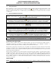
SUPER RUNNER SERIES GAS FRYERS CHAPTER 1: INSTALLATION INSTRUCTIONS Frypot Assembly 1/2—3/4 Reducer Bushing Manifold Support Bracket Gas Valve Gas Burner Burner See Detail A 1.63-inch [41-mm] Orifice 1.30-inch [33-mm] Pressure Test Spigot Gas Manifold Orifice Gas Manifold Assembly Detail A Burner/Orifice Location Temperature Control Typical gas valve, burner and orifice locations (SR42 shown above). Propane Applications: 1.
SUPER RUNNER SERIES GAS FRYERS CHAPTER 2: OPERATION 2.1 Initial Startup Wash the unit and accessories thoroughly with hot, soapy water to remove any film residue, dust or debris. Rinse and wipe dry. Close the drain valve completely. Ensure the operating thermostat and high-limit thermostat sensing bulbs inside the frypot are securely seated in the holding clamp. 2.1.1 Operating the Gas Valve NON-CE UNITS ONLY: Rotate the knob counter-clockwise to the ON or PILOT positions.
SUPER RUNNER SERIES GAS FRYERS CHAPTER 2: OPERATION 5. Fill the frypot with oil, shortening or water to the bottom OIL LEVEL line scribed on the frypot back. Ensure heating tubes are covered in liquid prior to engaging burners. NOTE: If solid shortening is used, pack the shortening into the frypot, ensuring the shortening is packed beneath, between and above the tubes prior to operating fryer. 6.
SUPER RUNNER SERIES GAS FRYERS CHAPTER 2: OPERATION DANGER "Dry-firing" the fryer will cause damage to the frypot and can cause a fire. Always ensure that shortening, cooking oil or water covers the burner tubes before lighting the burners. 2. With the pilot lit, push down and slowly turn the gas valve knob to the ON position. 3. Rotate the operating thermostat knob to the desired frying temperature. The burner should light and burn with a strong blue flame.
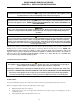
SUPER RUNNER SERIES GAS FRYERS CHAPTER 2: OPERATION 2.5 Wiring Diagram CE UNITS ONLY: WARNING DO NOT CONNECT ANY EXTERNAL ELECTRICAL POWER TO THIS UNIT TH PP PP TH THERMOPILE HONEYWELL 807-3565 OPERATING THERMOSTAT COAXIAL LEAD TO THERMOCOUPLE 812-1284 HIGH-LIMIT HONEYWELL CE NON-CE UNITS ONLY: CONTROL CIRCUIT PILOT GENERATOR HONEYWELL 1/2 P.S.I. PILOT C 3C HONEYWELL 1/2 P.S.I. PILOT ADJ. ON 4C 1/2 P.S.I.
THIS PAGE INTENTIONALLY LEFT BLANK
Dean, 8700 Line Avenue, PO Box 51000, Shreveport, Louisiana 71135-1000 Shipping Address: 8700 Line Avenue, Shreveport, Louisiana 71106 TEL 1-318-865-1711 PRINTED IN THE UNITED STATES FAX (Parts) 1-318-219-7140 FAX (Tech Support) 1-318-219-7135 Price: $10.