
Installation manual

27
ASSEMBLY PROCEDURE
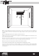
1. Position the paper template supplied on the wall and using a pencil mark
the position of the opening to be made in the wall at a height of around 200
cm from the floor and 15 cm from the ceiling (see the recess outline on the
reference template).
Unusual installation positions must be worked out case by case.
Whenever the paper template has not been provided, see the
dimensions shown in the drawing on Page 11.
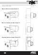
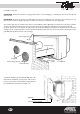
2 Make an opening of adequate depth in the wall bearing in mind that the
unit's recessed section has a maximum depth of 23.5 cm and a minimum
depth of 18 cm (see Figures 3 and 4).
3. Consulting the reference measurements provided on the template, drill
adequate holes for the suction and expulsion of the air using drill bits.
These holes must slope slightly downward by approximately 0.5 cm from
the inside to the outside in order to prevent rain or dirt from entering the
room and the air conditioner.
3a. Consider the idea of preparing a compartment for the air conditioner's
power supply inside the opening in the wall, making sure that it will not
create problems subsequently during the insertion of the unit.
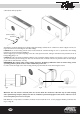
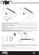
4. Insert the plastic pipes of diameter and length adequate to the depth of
the wall into the holes drilled for air suction and expulsion, making sure that
the pipe lined with condensate-proof material can be fitted into hole A as
shown in Figure 1.
N.B.: The air inlet and outlet pipes supplied have a maximum length of 40
cm; for this reason, if the depth of the wall is less, these pipes must be cut.
For installations with pipes longer than 40 cm, please contact your nearest
Technical Assistance Center or your Manufacturer's technical/commercial
contact person.
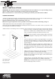
5. Make sure that the air expulsion pipe (hole A in Figure 1) is lined with
condensate-proof insulation material along its entire length.
Whenever the kit supplied is not used, remember to internally line the air
expulsion pipe (to be fitted in hole
A in Figure 2) with condensate-
proof material for its entire length.
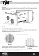
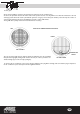
6. Apply junk rings or appropriately
insulated flanges on the pipes in
order to guarantee ideal contact
between the air conditioner and
the holes (see Figure 5).
IMPORTANT: the cut flange must
be applied near hole A shown in
Figure 2 where the insulated pipe
will be connected. .
BUILT-IN INSTALLATION
IMPORTANT: Make sure that the thickness and type of wall are adequate to flush-mount air conditioner installation.
IMPORTANT: Cordon off the outdoor area immediately beneath the installation area to prevent falling masonry
debris or chunks of plaster from damaging or injuring property and people below.
Make sure that there are no electric hoses or gas or water pipes inside the parts of the wall to be drilled.
figure 1
Approx. 200 cm
23,5 cm 18,5 cm
fig. 3
fig. 5
fig. 4
figure 2
A
B
A air expulsion hole
B air suction hole