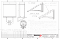
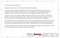
| 2 em conman same man L LESS THAN LENGTH DIMENSION OF THE EQUIPMENT INSTALLED fF T mem mmm mmm 86017 pn EX Lo WALL BRACKET TYPICAL ACB SYSTEM UNLESS OTHERWISE BREED, DIMENSIONS ARE IN INCHES [MILLIMETERS] CES AME: ANGLES 31.
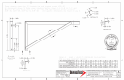
1.18in AC 0.150 NX G.15in i < SECTION C-C foe 1.600 1.15in 1 1.60in p— A i 0.15in B | [oso 1.60in 0.15in C SECTION A-A o Ailing, Sorter, To® IT 3 ccc S55 QoQ ort] Fonda JUN 17 B B Bracket Mounting 1.60In =e 0.15in Face | A { Max. Building Height {f)] 100 1.60in Tr Risk Category 1l il HAV 1/1 il I H/IvV iv il i Exposure] Max. Wind Speed (MPH)| 180 180 200 200 180 180 200 200 180 0.15 Max. Wind Pressure {fps] 63.1 86.2 90.4 107 81.4 94.8 100.5 | 117.1 94.
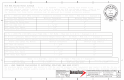
ACB Wall Mounting Bracket Installation Instructions — Professional Installation Required 1. Ensure that the supporting wall structure that the bracket will be mounted on is capable of supporting the weight of the air conditioner unit and bracket and can support the anchor loads as indicated on the ACB specification sheet. (PG-4) 2. Use the correct size wall mounting bracket (CAB-30, CAB-36, CAB-42 & CAB-48) to match up with the condenser unit size. Allow for a minimum of éin.