
Instructions / Assembly

CVENT-2
VERTICAL ROOF MOUNTING
NOTE: Roof mounting is recommended as it allows less intake
air contaminants and reduces ground-level exhaust.
1. Use furnace installation instructions to determine pipe
diameter.
2. Determine correct Concentric Vent size for the pipe
diameter selected.
3. Determine the best location for the Concentric Vent.
4. Cut a 4” diameter hole for CVENT-2, 2” kit.
5. Partially assemble Concentric Vent kit. Follow furnace
installation instructions for cleaning and cementing.
a. Cement “Y” tting to larger diameter air inlet pipe
(Figure 1).
b. Cement combustion air inlet cap to smaller diameter
pipe (Figure 1).
6. Install “Y” tting and pipe assembly through hole and roof
boot/ashing
(user supplied).
7. Secure to roof (Figure 3) using metal strapping or
equivalent support material (user supplied).
8. Install combustion air inlet cap and small diameter pipe
assembly into roof. Cement and bottom small diameter
pipe in “Y” concentric tting.
9. Cement furnace combustion air and vent pipes to
Concentric Vent. Refer to Figure 3 for proper pipe
attachment.
10. Check installation by allowing furnace to run through
one cycle.
NOTE: Keep assembly free of insulation during installation.
NOTE: Multiple Concentric Vent kits may be installed vertically
following the same clearances between vent outlets as
shown in Figure 6.
NOTE: Termination height must be above roof surface or
anticipated snow level (minimum 12” in U.S . or minimum 18”
in Canada) as shown in Figures 2 & 3.
NOTE: If assembly is too short, the 2 pipes supplied in the kit
may be replaced by using same diameter, eld supplied
SDR—26 PVC (D2241) pipe. Do not extend pipes with
Schedule 40 PVC or couplings. The additional wall thickness
will restrict combustion air and may cause operational
problems. Do not extend air inlet pipe more than 60” (Figure
3).
Do not use eld supplied couplings to extend pipes.
CAUTION:
Figure 3–Typical Roof Install
Maintain 12” minimum (18” for Canada) clearance above highest
anticipated snow level. maximum of 24” above roof.
Vent Combustion Air
Max 60”
Roof weather
Seal/Flashing
(eld supplied)
Combustion Air
Support
(eld supplied)
Elbow
(eld supplied)
HORIZONTAL SIDEWALL MOUNTING
NOTE: Refer to the following items before horizontal
installation:
• Check furnace installation instructions for
allowable clearances and locations.
• Refer to Figures 4 & 6 when venting multiple units
using multiple Concentric Vents.
• Avoid locations with high winds.
• Avoid locations where Concentric Vent is likely to
be damaged.
• Avoid locations where vapors are objectionable,
or may damage the structure, plants or air
conditioning condensing unit.
1. Use furnace installation instructions to determine
pipe diameter.
2. Determine correct Concentric Vent size for the pipe
diameter selected.
3. Determine the best location for the Concentric
Vent.
4. When installing multiple Concentric Vents, refer to
the following guidelines:
a. Do not install multiple Concentric Vents directly
above one another unless separated by a 3’
distance (minimum).
b. Install multiple Concentric Vents where the
horizontal distance between the ends of each
air intake is 4” or less or greater than 24”. This will
prevent a recirculation of ue gas.
5. Cut a 4” diameter hole for CVENT-2, 2” kit.
6. Partially assemble Concentric Vent kit. Follow
furnace installation instructions for cleaning and
cementing.
a. Cement “Y” tting to larger diameter air inlet pipe
(Figure 1).
b. Cement combustion air inlet cap to smaller
diameter pipe (Figure 1).
7. Install “Y” tting and pipe assembly through hole.
8. Install combustion air inlet cap and large diameter
pipe assembly. Cement and bottom small diameter
pipe in “Y” concentric tting.
9. Secure to structure (Figure 7) using metal strapping
or equivalent support material (user supplied).
10. Cement furnace combustion air and vent pipes to
Concentric Vent. Refer to Figure 7 for proper pipe
attachment.
11. Check installation by allowing furnace to run
through one cycle.
Figure 4–Sidewall Termination for
Multiple Vertical Concentric Vents
Figure 7–Sidewall Termination Details
NOTE: Securing strap must be eld installed to prevent
movement to termination kit in side wall
Vent
Combustion air
Strap (eld supplied)
Combustion air
Vent
Elbow
(eld supplied)
1” Combustion
air inlet
vanes to wall
Max 60”
Maintain 12” clearance
abovehighest anticipated
snow level or grade
Combustion air
Vent
Roof Overhang
12” Minimum
36” Minimum
1”
Figure 5–Sidewall Termination
Combustion air
Vent
Roof Overhang
12” Minimum
1”
Maintain 12” clearance
abovehighest anticipated
snow level or grade
Figure 6–Sidewall Termination for
Multiple Horizontal Concentric Vents
Combustion air
Vent
Roof Overhang
12” Minimum
1”
Maintain 12” clearance
above highest anticipated
snow level or grade
4” maximum or 24” minimum
(between end bell edges)
Do not use eld supplied couplings to extend pipes.
CAUTION:
NOTE: Keep assembly free of insulation during
installation.
NOTE: Maintain clearance dimensions as shown in
Figure 4, 5, 6 & 7.
NOTE: If assembly is too short, the 2 pipes supplied in
the kit may be replaced by using same diameter,
eld supplied SDR—26 PVC (D2241) pipe. Do not
extend pipes with Schedule 40 PVC or couplings. The
additional wall thickness will restrict combustion air
and may cause operational problems. Do not
extend air inlet pipe more than 60” (Figure 7).
Recirculation of ue gasses may occur, causing the
intake pipe to freeze shut during cold weather
operation if the venting system is not installed per
these guidelines. If the venting system is not installed
properly, ue gas may recirculate, possibly causing
the intake pipe to freeze shut during cold weather.
WARNING:
Concentric Vent Installation Instructions
CVENT-2 Concentric Vent Termination
For use with all condensing gas furnace models
General
The Concentric Vent allows both the intake for combustion air
and the exhaust vent to pass through a standard roof or
sidewall. This is an alternative to the standard two pipe
intake/vent shown in the basic furnace installation instructions.
Follow these instructions as well as the basic furnace
installation instruction for installation of the intake/vent pipe(s)
and all furnace installation procedures.
Refer to the furnace installation instructions for intake/vent
pipe sizing information.
NOTE: The Concentric Vent reduces the allowable intake/vent
piping length by 5 feet from that listed in the basic furnace
installation instructions.
Do not use the Concentric Vent kit for anything other than
a Category IV furnace. Failure to follow this warning
could result in re, personal injury or death.
WARNING:
Do not operate the furnace until the installation and
assembly of the Concentric Vent and all piping are
completed. Failure to follow this warning could result in
WARNING:
This kit contains the following parts:
(1) Combustion Air Inlet Cap
(1) Air Inlet Pipe
(1) Vent Pipe
(1) Intake/Vent Concentric “Y”
Pipe and ttings are required to complete installation (user
supplied). The combustion air and vent pipe ttings must
conform to ANSI and ASTM standards D1785, F891, D2665,
D2241, D2661, or F628. Pipe cement and primer must conform
to ASTM standards D2564 or D2235.
In Canada, construct all combustion air and vent pipes for
this unit of CSA or ULC certied Schedule 40 PVC, PVC-DWV, or
ABS-DWV pipe and pipe cement.
MODEL INTAKE/VENT NOM.
PIPE SIZE
OVERALL ASSEM’D
LENGTH
1
INTAKE PIPE OUTSIDE
DIAMETER
AIR INLET PIPE
LENGTH
2
CVENT-2 2” 34-3/4” 3-1/2” 19-1/2”
1. Shipping dimension. This may be eld modied by cutting or extending both the
intake and exhaust pipes. 12” is the minimum allowable length and 60” is the
maximum allowable length for this dimension. SDR-26 PVC (D2241) only may be
used for extending pipes. Do not extend pipes with Schedule 40 PVC or couplings.
2. This dimension will change if the intake/vent pipes are lengthened or shortened.
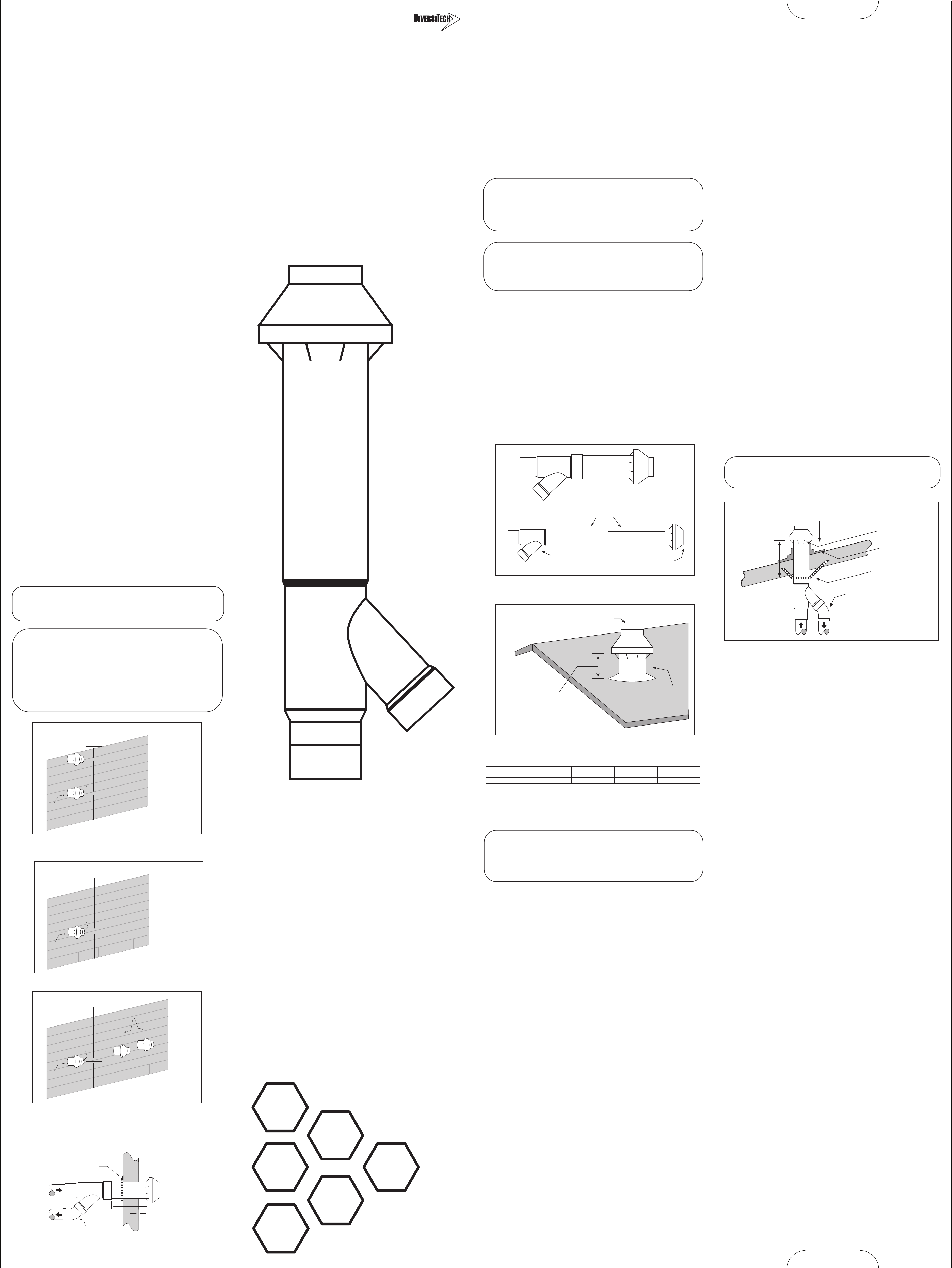
Figure 1–Vent Terminal Assembly
Assembled Terminal
“Y” Concentric Fitting
3” diameter
air inlet pipe
2” diameter
vent pipe
Combustion
air inlet cap
Figure 2–Typical Roof Installation
Vent
Combustion Air
Maintain 12”
minimum (18” for
Canada) clearance
above highest anticipated
snow level. maximum of 24”
above roof.
Some local code inspectors are not familiar with
concentric vents. Be sure to check local code
requirements and acceptability prior to installation.
NOTICE:
Concentric
Vent Kit – 2”
• Simplies the installation of
high eciency furnaces
• Requires only one hole to be
cut rather than two
• Saves time & money
during installation
DOC32185
L92-357
0 79 5 2 4 7 1 0 7 4 0
Made in Vietnam
H
L
W