
Install Instructions

1
2 3
4
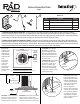
Item Description Quantity
1 Angle Bracket, 1-1/2” x 3.5”, Galvanized 2
2 Earth Anchor with Stainless Steel Cable 2
3 Screw, Self Tapping, #14, Stainless Steel 16
4 Drive Rod (Sold Separately) 1
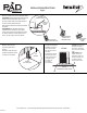
1 PREPARE THE PAD INSTALLATION SITE: The soil should have reasonable compressive strength (ICBO and UBC recommend a minimum
compressive bearing strength of 1,500 lb./sq. ft. for supporting pad). Anchor cable shall be driven into similar soil. Clear area of debris and vegetation
approximately six inches (6”) longer and wider than the pad itself. Rake the area level, sloping grade away from the pad site, to reduce the possibility of
water ponding around the pad. Anchoring system is designed for an AC unit with a maximum height of 42 inches.
1 PREARE EL SITIO DONDE VAYA INSTALAR LA BASE: La tierra debe tener una resistencia de compresión razonable. (ICBO y UBC recomiendan una
resistencia compresiva mínima de 1,500 lb./pie2 para la base de soporte). El ancla de tierra debe jarse en tierra de consistencia similar. Retire toda basura y
vegetación hasta unas 6 pulgadas más allá de lo largo y ancho de la base. Nivele el área con rastillo, dejando un pequeño declive para reducir la permanencia
de agua estancada alrededor de la base. El sistema de anclaje esta disanado para una unidad con altura de 42 pulgadas.
1
2
3
4
2 Position the
condenser on the
equipment pad
and position the
angle brackets to
be parallel to the
house.
2 Acomode el
condensador
sobre la base
del equipo,
asegurando que
las escuadras
queden paralelas
a la casa.
TAPE
MEAS.
CHECK MAX.
ALLOW
DIMENSION
VEIFIQUE
MÁXIMA
DIMENSIÓN
PERMITIDA
ANCHOR ORIENTATION PARALLEL TO THE HOUSE
ORIENTACIÓN DEL ANCLA PARALEALA A LA CASA
3 CAUTION: Do not puncture
the condenser coil. Drill tek
screws through the pre-drilled
holes on the angle bracket into
the base of the condenser unit
and into the pad. (Do the same
for the other side).
3 PRECAUCIÓN: Tenga cuidado
de no perforar la bobina del
condensador. A través de los
agujeros ya existentes en la
escuadra, atornille los tornillos
“tek” al fondo de la unidad del
condensador y a la base. (Haga
lo mismo del otro lado.)
OVERALL ANCHOR
HT. 28 INCH
20-24”
REQ. MIN. DEPTH
20-24” MIN.
SIDE VIEW
AC UNIT WITH ANCHOR
IMPORTANT: To ensure proper depth
of anchor, no more than 4 inches of
cable from the edge of the AC unit to
the edge of the pad can be exposed.
IMPORTANTE: Para asegurar la profundidad
adecuada del ancla, no podrán quedar
expuestos más de 4 pulgadas de cable desde
la orilla de la unidad hasta la orilla de la base.
4 Place drive point as close
to the pad as possible and
begin driving anchor until the
cable has adequate tension.
In order to limit sliding, drive
anchor at a 20 to 30 degree
angle away from pad.
4 Coloque el punto de
impulso lo más cerca posible
a la base y je el ancla hasta
lograr una tensión adecuada
en el cable. A n de reducir
el deslizamiento, coloque el
ancla a un angulo de 20 a 30
grados de la base.
DRIVE ROD
(BARRA DE IMPULSIÓN)
TEK SCREW
(TOMILLO “TEK”)
ANGLE
BRACKET
(ESCUADRA)
ANGLE
BRACKET
(ESCUADRA)
EARTH ANCHOR
(ANCIA DE TIERRA)
Parts List
INSTALLATION INSTRUCTIONS
Page 1
AC ANCHOR SYSTEM
TOP VIEW
A/C UNIT WITH ANCHOR SYSTEM