QUICK INSTALLATION GUIDE HDB-M120 Full HD NETWORK CAMERA 1
DESCRIPTION ------------------------------------------------------------------------------------------------------------------------------------The HDB-M120 Series camera is an internet protocol based megapixel network camera with a builtin web based viewer on Internet Explorer®. The camera has a connection feature for third-party applications and compatible with supplied Utility software for easy installation and Client software to search, configure, manage, live view, record and playback.
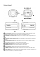
Camera Layout RJ-45 connector: Supplies power to the camera through the network using PoE. If PoE is not available, supplies DC12V or AC24V power source to the POWER connector. ETHERNET link indication LED: Flashes green to indicate that data is being TX/RX by the camera. ETHERNET activity indication LED: Glows solid amber to indicate that a live connection is established.
Please 1. 2. 3. 4. take steps as follows: Power off Press and hold the RESET button Supply the camera with power Hold the RESET button for 15 seconds ALARM connection: Connect one or two physical alarm input signal into the device and one alarm output signal that can be used to control an external alarm circuit. BNC connector: Connect BNC cable for composite video output. INSTALLATION TOP STAND connector: 0.25 Inch (0.64cm) UNC-20 screw, top of camera housing. INSTALLATION BOTTOM STAND connector: 0.
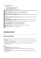
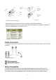
- Recommend to install the megapixel lens from the following lens manufactures. -- TAMRON -- COMPUTAR -- FUJINON Starting Installation 1. Install the Lens - Be careful the lens does not touch camera sensor when installer try to enter the lens into camera. - Install manual lens or DC auto iris lens. - If DC auto iris lens needs to install, connect DC auto iris 4-pin connector into iris drive connector located on the side of the camera. 2.
[4-Pin iris driver connector] - Attach the DC-type auto iris lens to the lens mount on the front of the camera. - Plug the connector into the auto iris jack on the side of the camera. The connector is polarized and can be inserting into the iris jack one way. [DC auto iris Lens connection] Audio Connection This camera supports bidirectional audio. Install the microphone and speaker which has an amplifier capability.
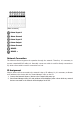
[Alarm connector] Alarm Input 1 Alarm Ground Alarm Input 2 Alarm Output Alarm Ground RS485 RS485 + Network Connection The Network Camera supports the operation through the network. Therefore, it is necessary to connect a standard RJ-45 cable to it. Generally a cross-over cable is used for directly connection to PC, while a direct cable is used for connection to a hub. IP Assignment When a camera is first connected to the network it has no IP address.
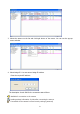
3. Select the camera on the list and click right button of the mouse. You can see the pop-up menu as below. 4. Select Assign IP. You cam see an Assign IP window. Enter the required IP address. The description of each field for the connection status follows. : Available for connection to the camera : Loading settings information of video after connecting the camera.
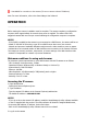
: Unavailable for connection to the camera (PC can not access relevant IP Address) Note: For more information, refer to the Smart Manger User’s Manual. OPERATION ------------------------------------------------------------------------------------------------------------------------------------Before starting the camera, installation must be complete. The camera completes a configuration sequence within approximately 40 seconds when power is supplied.
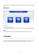
- Click the Live View icon for default live image view or the Setup icon to change the configuration values. Main Menu [Main Menu] The dialog box will be appears. - Type User ID and Password in the dialog box. The default User ID and Password are admin. NOTE For security purposes, be sure to change the password after you log on for the first time.
[ Main Live View Page] Live Video Page Icons Hide Main Icons: Hides main icons in the live view page. Show Main Icons: Shows main icons in the live view page. Live view: Displays live video stream. Playback View: Enters playback menu. Setup: Enters setup menu. Help: Shows helpful information. Source: Specify the viewable video stream source to display in live view page. View Size: Specify the viewable video size to display in live view page.
ROI View: Specify the specially selected area to transfer using different stream feature in the primary video image. ROI is an abbreviation for “Region of Interest”. Preset: Specify the Preset. This icon is inactivated if the PTZ settings are not set. Pause: Pause the live video stream. Snapshot: Take a picture of the video image currently on display. Supports the origin image size view, Print, and Save feature. Digital Zoom: Supports a digital zoom in live video image.
→ If using a proxy server, try disabling the proxy setting in your browser. Check all cabling and connectors. 2. The camera works locally, but not externally. → Check if there are firewall settings that need to be adjusted. Check if there are router settings that need to be configured. 3. Poor or intermittent network connection. → If using a network switch, check that the port on that device uses the same setting for the network connection type (speed/duplex). 4.
NOTE If you cannot find the help you require, please see the User's Manual, or contact with your network administrator.