Ichill 200CX EVO rev 1.1 14/11/2013 Ichill 206CX EVO Ichill 208CX EVO (Firmware version 4.0) Pag.
Ichill 200CX EVO rev 1.1 14/11/2013 INDEX 1. GENERAL FEATURES .............................................................................................. 6 2. ICHILL 206CX/IC208CX FEATURES......................................................................... 6 3. USER INTERFACE .................................................................................................... 7 4. REMOTE TERMINAL ...............................................................................................
Ichill 200CX EVO rev 1.1 14/11/2013 22. COMPRESSOR RACK ............................................................................................. 48 23. COMPRESSORS WITH DIFFERENT CAPACITY POWER ..................................... 49 24. CIRCUIT MANAGEMENT: SATURATION OR BALANCING .................................. 49 25. PUMP DOWN ........................................................................................................... 49 26. UNLOADING ...................................
Ichill 200CX EVO rev 1.1 14/11/2013 45. CONDENSER TEMPERAURE / PRESURE CONDITION TO ENABLE/DISABLE THE RECOVERY CYCLE ................................................................................................. 90 46. OPERATION RELATED TO THE REAL TIME CLOCK ........................................... 90 47. MESSAGES - ALARM CODES ............................................................................... 91 48. MANUAL ALARM PROCEDURE.........................................................
Ichill 200CX EVO rev 1.1 14/11/2013 General advice PLEASE READ BEFORE USING THIS MANUAL • This manual is part of the product and should be kept near the instrument for easy and quick reference. • The instrument shall not be used for purposes different from those described hereunder. It cannot be used as a safety device. • Check the application limits before proceeding • The technical data and information in the user manual could change without obligation to notice.
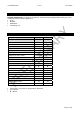
Ichill 200CX EVO rev 1.1 14/11/2013 1. GENERAL FEATURES IC206CX_IC208CX EVO is an electronic controller for chiller and heat pump applications having one or two circuits; the Ichill has specific regulation for: • Air/air • Air/water • Water/water • Condensing unit 2. ICHILL 206CX/IC208CX FEATURES FEATURES IC206CX IC208CX OUTPUT RELAYS 6 n 8 n DIGITAL INPUTS 11 (free voltage) configurable configurable 4 (NTC/PTC) configurable configurable 2 (NTC/PTC/0..5V/4..
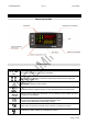
Ichill 200CX EVO rev 1.1 14/11/2013 3. USER INTERFACE Meaning of the LEDs Display and Icons ICON °C -°F BARPSI MEANING / FUNCTIONNING ON when a temperature or pressure is visualized ON when the compressor is active Blinking = when a compressor activation is delayed (minimum OFF time, delay after water pump activation, etc.
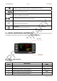
Ichill 200CX EVO rev 1.1 14/11/2013 Domestic hot water: ON when domestic hot water production is active ON when menù button is pressed AUX ON when an auxiliary output is active ON if the Ichill is swithed ON in cooling or heating ON when the free cooling is active FC ON in defrost Blinking during defrost activation delay 3.1 UPPER & LOWER DISPLAY CUSTOMIZATION It is possible to select wich probe has to be visualized on the upper & lower display.
Ichill 200CX EVO rev 1.
Ichill 200CX EVO 3.2 rev 1.1 14/11/2013 14 domestic hot water temperature 2 SAn2 15 solar panel temperature SoLE 16 condenser temperature 17 condenser pressure 18 evaporator pressure 19 compressor oil pressure 20 real time clock Cdt1 circuit 1 Cdt2 circuit 2 CdP1 circuit 1 CdP2 circuit 2 LP1 circuit 1 LP2 circuit 2 FORCED READ - OUT OF THE TOP AND BOTTOM DISPLAY The dP03 parameter allows to have a pre-defined visualization.
Ichill 200CX EVO rev 1.
Ichill 200CX EVO 3.3 rev 1.1 14/11/2013 HOW TO READ COMPRESSOR STATUS if a compressor is disable for maintenance the display shows: compressor 1 disabled: label c1ds compressor 2 disabled: label c2ds compressor 3 disabled: label c3ds compressor 4 disabled: label c4ds 3.
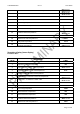
Ichill 200CX EVO 3.2 rev 1.1 14/11/2013 KEY COMBINANTION KEY + + + ACTION Push for 3 seconds together Only in Pr3 level: push SET and DOWN key Push once together Push 5 seconds in heat pump mode FUNCTION Enter the programming parameters Select the parameter level visibility Pr1 / Pr2 / Pr3 Exit the programming parameters Manual defrost Only in Pr3 programming level: In Pr3 defines if the parameter can be modified or push SET and then the MENU key not in the other levels. 4.
Ichill 200CX EVO rev 1.1 14/11/2013 2. Push SET one time: the value is blinking 3. Use the Up and Down keys to adjust it. Push SET one time to confirm; automatically the display shows next parameter 4. Repeat the operations 2. 3. and 4. for all the RTC parameters: - Min: minutes (0÷60) - UdAy: day of the week (Sun = Sunday, Mon =Monday, tuE =Tuesday, UEd = Wednesday, tHu = Thursday, Fri =Friday, SAt =Saturday) - dAy: day of the month (0÷31) - MntH: month (1÷12) - yEAr: year (00÷99) 6.
Ichill 200CX EVO rev 1.1 14/11/2013 Enter the Pr1 - Pr2 - Pr3 programming levels Pr1 LEVEL: Push SET + DOWN together for 3 seconds, the top display shows the PAS label and the bottom display shows the Pr1 label. The leds cir1/cir2 are blinking (up and down leds) to inform that you now are in PR1 programming level. Pr2 LEVEL: From the Pr1 level push the UP key for 2 seconds and the bottom display will show Pr2. The top display still shows PAS.
Ichill 200CX EVO rev 1.1 14/11/2013 3. Push SET key and the top display shows a blinking 0, with UP or DOWN insert the Pr2 password. Push SET and, if the value is correct, top display will show the first family of parameters “ALL”. Otherwise set the password again. 4. Select a parameter family with DOWN or UP keys. 5. Push SET to enter, the bottom display shows the first available parameter label while the top display shows its value.
Ichill 200CX EVO • • • • • • • • • rev 1.1 14/11/2013 Leds 1 / 2 are blinking: the parameter can not be changed. All the leds are off: the parameter is available only in Pr3. Led 4 on: the parameter can be changed also in Pr2. Led 4 blinking: the parameter is visible also in Pr2 . Leds 3 / 4 on: the parameter is available in Pr2 and in Pr1. Leds 3 / 4 blinking: the parameter is visible in Pr1 and in Pr2. The MENU key allows to exit from a family to reselect another without exit the Pr2 level.
Ichill 200CX EVO rev 1.1 14/11/2013 1. Enter Pr3 level 2. Select a whatever parameter family 3. Search “Pr3” label; push SET key to change the value that now is blinking. 4. Use UP or DOWN key to insert the NEW PASSWORD value, then push SET to confirm the new value. 5. The top display blinks for some seconds and then shows the next parameter 6. Exit the programming pushing SET + UP together or wait the timeout. Inside the Pr3 level it is possible to change also the Pr1 and Pr2 passwords.
Ichill 200CX EVO rev 1.1 14/11/2013 Letter can be: o (open) = function associated to the input or output is active when the contact is open c (close) = function associated to the input or output is active when the contact is closed The number defines the function associated to the input or output.
Ichill 200CX EVO rev 1.1 14/11/2013 Fig.2: upper display shows outlet 2 evaporator temperature, the lower display shows Out2. Pressing SET key is possible to read the same probe of the first circuit. Fig.2 9. DISPLAY INFORMATION Read Set Point value Push and release the SET key, the leds of the circuits are off and the set value is displayed. In stand-by the bottom display shows SetC (set chiller), by pushing SET again the next label is SetH (set heat pump ).
Ichill 200CX EVO rev 1.1 14/11/2013 10.
Ichill 200CX EVO rev 1.1 14/11/2013 the UP or DOWN keys to scroll all the alrm list (nothing happens by pushing SET when the label NO is displayed). 3. Pushing SET when the rSt label is displayed; the corresponding alarm will be reset 4. To exit the Alrm function push MENU or wait the timeout. 5. Repeat operation 1 – 4 to reset the other alarms.
Ichill 200CX EVO rev 1.1 14/11/2013 THE ALARM LIST CONTAINS 100 EVENTS IN A FIFO STRUCTURE. WHEN THE MEMORY IS FULL ANY NEW ALARM WILL ERASE THE OLDEST. Disable – enable a circuit CrEn FUNCTION. Label involved with CrEn function: Cr1E = circuit 1, Cr2E = circuit 2 DISABLE A CIRCUIT Enter the function Menu 1. Use UP or DOWN keys to select CrEn on the bottom display 2. Push SET key: the bottom display Cr1E, top display En. 3. Select the circuit 1 or 2 with UP or DOWN (Cr1E or Cr2E). 4.
Ichill 200CX EVO rev 1.1 14/11/2013 The running hours is displayed on the top display, the resolution is x 10 hours (eg 2 means 20 hours, 20 means 200hours) Enter the function Menu 1. 2. 3. 4. Use the UP or DOWN keys to select Hour Push SET key: bottom display = above labels, top display = hours x10. The time Use the UP or DOWN keys to scroll the list. To exit the Hour function push MENU key or wait the timeout is on. Reset the running hour Enter the function Menu 1.
Ichill 200CX EVO rev 1.1 14/11/2013 Pou4 Proportional output for dumper control or to drive the external relay 4 ICX207D outputs (I/O expansion): PoE1 Proportional output for dumper control or to drive the external relay 1 PoE2 Proportional output for dumper control or to drive the external relay 2 PoE3 Proportional output for dumper control or to drive the external relay 3 The labels are displayed only if the corresponding output is present and configured.
Ichill 200CX EVO rev 1.1 14/11/2013 2. Push SET key: the label uSt1 (temperature probe ) or uSP1 (Pressure probe) is showed on bottom display, the top display shows the the temperature or pressure value. 3. Use the UP or DOWN keys to select uSt1 auxiliary probe for circuit 1or uSt2 auxiliary probe for circuit 2. 4. To exit the Hour function push MENU key or wait the timeout.
Ichill 200CX EVO rev 1.1 14/11/2013 After the number 28 the configuration can be selected from o 1 to c75 that allows to set an analogue input as digital input (see polarity of the digital input/outputs).
Ichill 200CX EVO 17. 18. 19. 20. 21. 22. 23. 24. 25. 26. 27. 28. 29. 30. 31. 32. 33. 34. 35. 36. 37. 38. 39. 40. 41. 42. 43. 44. 45. 46. 47. 48. 49. 50. 51. 52. 53. 54. 55. 56. 57. 58. 59. 60. 61. 62. 63. 64. 65. 66. 67. 68. 69. 70. 71. 72. 73. 74. 75. rev 1.
Ichill 200CX EVO 0. 1. 2. 3. 4. 5. 6. 7. 8. 9. 10. 11. 12. 13. 14. 15. 16. 17. 18. 19. 20. 21. 22. 23. 24. 25. 26. 27. 28. 29. 30. 31. 32. 33. 34. 35. 36. 37. 38. 39. 40. 41. 42. 43. 44. 45. 46. 47. 48. 49. 50. 51. 52. 53. 54. 55. 56. 57. 58. 59. rev 1.
Ichill 200CX EVO 60. 61. 62. 63. rev 1.1 70. 71. 72. 73. 74.
Ichill 200CX EVO o rev 1.1 14/11/2013 Remote keyboard (LED or LCD depending from the Ichill model). 11.2 I/O EXPANSION INPUT/OUTPUT CONFIGURATION Analog input Pb1 - Pb2 – Pb6 – Pb7– Pb8 0. Not enabled 1. Temperature probe PTC for compressor 1 discharge 2. Temperature probe PTC for compressor 2 discharge 3. Temperature probe PTC for compressor 3 discharge 4. Temperature probe PTC for compressor 4 discharge 5. Not used 6. Not used 7. Temperature probe PTC for solar panel 8.
Ichill 200CX EVO rev 1.
Ichill 200CX EVO 42. 43. 44. 45. 46. 47. 48. 49. 50. 51. 52. 53. 54. 55. 56. 57. 58. 59. 60. 61. 62. 63. 64. 65. 66. 67. 68. 69. 70. 71. 72. 73. 74. rev 1.
Ichill 200CX EVO 27. 28. 29. 30. 31. 32. 33. 34. 35. 36. 37. 38. 39. 40. 41. 42. 43. 44. 45. 46. 47. 48. 49. 50. 51. rev 1.1 70. 71. 72. 73. 74.
Ichill 200CX EVO 7 8 9 rev 1.1 14/11/2013 Proportional output for modulating compressor 2 Condenser fan circuit 1 Condenser fan circuit 2 After selection number 9 it is possible to configure the analog output as digital output with the same meaning of the relays configuration; every analog output can be configured from “o 1” to “c50” (see relay configuration table). Proportional output configuration OUT 3 and OUT 4 (0 ÷ 10 Vdc / 4..
Ichill 200CX EVO rev 1.1 14/11/2013 13. HOW TO SWITCH ON / SWITCH OFF THE UNIT SWITCH ON / SWITCH OFF THE ICHILL BY KEYBOARD Push and release the key allows to start in chiller mode if CF58 =0, in heat pump if CF58 =1. When the unit is running the corresponding led is on. INPORTANT: To change from chiller to heat pump and viceversa the unit must be set in stand-by before continuing. Push and release the key allows to start in heat pump mode if CF58 =0, in chiller if CF58 =1er.
Ichill 200CX EVO rev 1.1 14/11/2013 With active contact if the unit is being switched off by keyboard it can be switched on by keyboard. If the unit is being switched off by keyboard, in order to switch on the unit from digital input it must be deactivated and activated. DIGITAL INPUT CONFIGURATED AS HEAT PUMP REQUEST The machine has to be configured as condensing unit CF03 = 1.
Ichill 200CX EVO rev 1.1 14/11/2013 Keyboard selection CF58 = 0: pushing key the unit starts in chiller, pushing key the unit starts in heat pump CF58 = 1: pushing key the unit starts in heat pump, pushing key the unit starts in chiller Analog input selection CF58 = 0 NTC, External air temperature probe > CF60+ CF61 temperature probe < CF60 the unit starts in heat pump. CF58 = 1 NTC, External air temperature probe > CF60+ CF61 the unit starts in heat pump.
Ichill 200CX EVO rev 1.1 14/11/2013 Par. ST08 Regulation band in heat pump mode Par. ST09 Defines the thermoregulation probe in chiller. Par. ST10 parameter defines the thermoregulation probe of the unit with heat pump control Par. ST11 defines the type of regulation St11 = 0 Proportional regulation St11 = 1 Neutral zone regulation 17.2 Proportional Regulation Cooling regulation Heating regulation 17.3 Neutral Zone Regulation Compressor regulation in chiller Pag.
Ichill 200CX EVO rev 1.1 14/11/2013 Compressor regulation in heat pump Compressor in neutral zone Par. CO53 Maximum time of work in neutral zone without resource insertion Pag.
Ichill 200CX EVO rev 1.1 14/11/2013 When the temperature is inside the neutral zone, a timer is activated (parameter CO53); when this time is elapsed, the Ichill switch on all the compressor to avoid an stationary situation. If the parameter value is 0 the function is non activated. Par.
Ichill 200CX EVO rev 1.1 14/11/2013 Fig 2 Part Winding start- up of Compressors or capacity compressors If one or more capacity compressors are configured and the thermoregulation requires the full load start-up: the controller turns the solenoid valve on, after 1 second the first motor part of the 1st compressor (relay K1 of Fig. 2) and then the complete control with the contactor K2. Durning the CO13 time delay the step valve is forced on: minimum power.
Ichill 200CX EVO rev 1.1 14/11/2013 0% 25 % 50 % 75 % 100 % CO06 = 1 direct action Eg: compressor with 3 capacity step. Capacity Compr. Out relay Out relay Out relay 25% Compressor ON Cap. step 1 ON Cap. step 2 OFF Cap. step 3 OFF 50% Compressor ON Cap. step 1 ON Cap. step 2 ON Cap. step 3 OFF 75% Compressor ON Cap. step 1 ON Cap. step 2 ON Cap. step 3 ON 100% Compressor ON Cap. step 1 OFF Cap. step 2 OFF Cap. step 3 OFF 75% Compressor ON Cap. step 1 ON Cap. step 2 OFF Cap.
Ichill 200CX EVO Compressor Cap. step 1 rev 1.1 Cap. step 2 Cap. step 3 14/11/2013 Power 0% 25 % 50 % 75 % 100 % ATTENTION When working with capacity control in sequential step in direct or reverse modes: if the power requested is 50% and 75% the unit turn on also the step 25% that must be enabled to make run the other two. 20.1 Minimum Load Start- Up Par. CO07: configuration of the start-up with minimum load.
Ichill 200CX EVO rev 1.
Ichill 200CX EVO rev 1.1 14/11/2013 TWO COMPRESSORS INVERTER CONTROLLED OPERATING MODE: CHILLER TWO COMPRESSORS INVERTER CONTROLLED OPERATING MODE: HEAT PUMP Pag.
Ichill 200CX EVO rev 1.
Ichill 200CX EVO rev 1.1 CO81 Maximum speed of the inverter compressors in sanitary water CO82 Outside temperature to reduce inverter compressor speed in Heat pump CO83 Hysteresis temperature to reduce inverter compressor speed in Heat pump CO84 Compressor speed if outside temperature > CO82 14/11/2013 100 % 70.0 158 50.0 725 °C °F Bar Psi Dec int Dec int 25.0 45 14.0 203 100 °C °F Bar Psi % Dec int Dec int 1 50.0 -58 0.0 0 0.1 0 0.1 1 0 21.
Ichill 200CX EVO rev 1.1 14/11/2013 23.
Ichill 200CX EVO rev 1.1 14/11/2013 Low pressure alarm (when the low pressure switch is used) is disabled for AL02 time after valve activation (AL02=0 the alarm is disabled when the compressor is OFF). When first compressor of the circuit is switched on, the solenoid valve is switched on 1 seconds before it.
Ichill 200CX EVO rev 1.1 14/11/2013 AL23=1 manual reset; if the number of pump down alarm per hour is lower than AL22 the reset is automatic, manual reset; if the number of pump down alarm per hour is higher than AL22 the reset is manual CO36 = 3 Pump down enabled during the switching off only in chiller mode(low pressure probe) The pump douwn procedure works as CO36=1 but only in chiller mode; in heat pump mode the solenoid valve is activated when the first compressor is ON and de-.
Ichill 200CX EVO rev 1.1 14/11/2013 26.2 Condenser High Pressure, Condenser High Temperature Or Evaporator Low Pressure UNLOADING ACTIVATION IN CHILLER MODE When the condenser pressure or temperature is higher than CO44 the unit works with the number of compressors selected in CO49 parameter or CO96 speed in case of inverter compressor. If the compressor is a screw compressor the unloading function works at least CO50 time; if CO50 = 0 this function is disabled.
Ichill 200CX EVO rev 1.1 14/11/2013 Unloading function is disabled when the temperature of all the probes configured rise over CO55 + CO56 or when the CO57 time is elapsed. 27. SOLENOID VALVE FOR LIQUID INJECTION It is possible to configure 2 valves for the liquid injection of the screw compressor (compressor 1 and compressor 2). When the compressor is off the solenoid valve is always OFF.
Ichill 200CX EVO rev 1.1 14/11/2013 28.2 Modulating Evaporator Water Pump To enable the modulating evaporator water pump is necessary to configure an analog output as “Modulated evaporator water pump” (see analog and digital output configuration) . The modulating evaporator water pump is enabled in cooling, heating and sanitary hot water production; if the machine is in STD-BY or OFF the water pump is OFF.
Ichill 200CX EVO rev 1.
Ichill 200CX EVO rev 1.1 14/11/2013 29.1 Condenser Pump Group It is possible to configure two condenser water pumps; the water pump to be activated is the pump with less working hours. When a water pump works continuosly for CO24 time, the other one is switched on and after CO25 second the first one is switched off. If a water pump overload occurs, the water pump is switched off and the other one is switched on. 30.
Ichill 200CX EVO rev 1.1 14/11/2013 32. LOAD MAINTENANCE It is possible to define for each load (compressors and water pumps) the number of working hours after witch the display will show a maintenance warning. Parameters CO26..CO29: number of working hour of the compressors Parameters CO32..CO33: number of working hour of the evaporator water pump Parameters CO34..
Ichill 200CX EVO rev 1.1 14/11/2013 Fans on, with ON/OFF regulation and with temperature/pressure transducer control, only when the compressor is on (at least one relay is configured as fan control). When the compressor turns off the fans are thermoregulated depending on the condensing temperature/pressure. Par. FA01 = 3 / Par.
Ichill 200CX EVO rev 1.1 14/11/2013 33.3 Condensing Unit: Common Or Separate Condenser FA05 defines the condenser unit Par.
Ichill 200CX EVO rev 1.1 14/11/2013 Condenser fan in Heat pump mode. 33.6 Pre-Ventilation And Post-Ventilation Pre-ventilation: in chiller and heat pump mode when first compressor is swtiched on if FA06>0 and/or FA30>0 the fan runs at maximum speed for FA06 and/or FA30. Post-ventilation: in heat pump mode if FA31>0 and outside temperature > FA32, when last compressor is switched off the condenser fan (if on at that moment) is forced at FA33 speed for FA31 seconds (outside temperature probe is required).
Ichill 200CX EVO rev 1.1 14/11/2013 Regulation of the heaters in heat pump The Par. Ar07 selects the probe/s control for the anti-freeze alarm and the relay outputs configured as antifreeze / support / boiler heaters for the circuits 1 and 2 in heat pump mode. Par. Ar07 = 0: the function is disabled Par. Ar07 = 1: function enabled; the regulation probe is evaporator water inlet. Par.
Ichill 200CX EVO rev 1.1 14/11/2013 When outside temperature decreases under the Ar12 setpoint, the Ar14 delay starts counting. If during the Ar14 counting the external air increases above the Ar12 + Ar13 (differential) the function is aborted and the Ar14 time is reloaded.
Ichill 200CX EVO rev 1.1 14/11/2013 key. The real value of the set point is showed pressing the When the Energy Saving function is activated the chiller set point and heat pump are modified as follow: • Set point chiller = St1 ± ES14 • Chiller differential = ES15 • Set point heat pump = St4 ± ES16 • Heat pump differential = ES17 How to program the Energy saving and how to Switch on / Switch off the Ichill by RTC Enter the parameter programming: 1. Select the ES parameter family. 2.
Ichill 200CX EVO rev 1.1 14/11/2013 MONDAY X = 3 - Y= 7: the energy saving is enabled in time band 1 and time band 2, the automatic on is enabled in time band 1, time band 2 and time band 3. WEEKLY PROGRAMMING Repeat the daily programming for the other days of the week using parameters ES08..ES13.
Ichill 200CX EVO rev 1.1 14/11/2013 Analog input configured as outside temperature and positive differential: Analog input configured as outside temperature and negative differential: Pag.
Ichill 200CX EVO rev 1.1 14/11/2013 37. AUXILIARY RELAYS Par. uS01 configuration auxiliary relay 1 Par. uS05 configuration auxiliary relay 2 0 = Not enabled 1 = Function enabled, direct action, also if the Ichill is in stand-by or remote off.
Ichill 200CX EVO rev 1.1 US 6 Auxiliary relay 1 winter minimum set point 14/11/2013 -30.0 -22 0.0 0 US8 US8 70.0 158 50.0 725 US6 US7 0.1 0 0.1 1 0.1 0 0.1 1 25.0 45 14.0 203 25.0 45 14.
Ichill 200CX EVO rev 1.1 14/11/2013 Par.
Ichill 200CX EVO US 22 US 23 rev 1.1 Auxiliary proportional output n° 1 operating mode 0= Not enabled 1= Always available with direct action 2= Available only when the unit is on with direct action 3= Always available with reverse action 4= Available only when the unit is on with reverse action Analogue input configuration for auxiliary control 1 Allows to select which probe value Pb1..Pb10 controls output US 24 Analog output 1 summer minimum set point 14/11/2013 0 4 1 10 -30.0 -22 0.
Ichill 200CX EVO rev 1.1 US 36 Analog output 2 summer minimum set point 14/11/2013 -30.0 -22 0.0 0 US38 US38 70.0 158 50.0 725 US36 US37 -30.0 -22 0.0 0 US41 US41 70.0 158 50.0 725 US39 US40 0.0 0 0.0 0 0.0 0 0.0 0 0 US44 0 25.0 45 14.0 203 25.0 45 14.
Ichill 200CX EVO rev 1.1 14/11/2013 When the condenser temperature/pressure or evaporating pressure falls below dF02 and at least one compressor is ON, the delay between two defrost dF09 starts counting. The display of the keyboard shows the symbol blinkking. dF09 counter is reloaded in case of power down, after a defrost cycle, when the Ichill change the operation mode (from heat pump to chiller) or when the Ichill is in STD-BY or remote OFF.
Ichill 200CX EVO rev 1.1 14/11/2013 39.3 Forced Defrost The function is enabled if the parameter dF19>0. It allows to make a forced defrost cycle even if the dF09 timeout counting is not expired, when the condensing/evaporating temperature/pressure is lower than dF20 setpoint for the dF19 time counting. If during the dF19 time counting the condensing/evaporating temperature/pressure rises above the value dF20+dF21 (set+differential) the function is disabled and the tF19 time is reloaded.
Ichill 200CX EVO Parameter dF22=0 dF22=1 dF22=2 rev 1.1 dF23=0 YES YES not possible (ACF1) dF23=1 not possible (ACF1) YES YES 14/11/2013 dF23=2 not possible (ACF1) YES not possible (ACF1) ATTENTION: The configuration error ACF1 is displayed if the parameter value of dF22 and dF23 is not permitted. For only one condensing unit the dF22 and dF23 values must be not equal to 0. 39.
Ichill 200CX EVO rev 1.1 14/11/2013 If dF01=2, it determines the maximum duration of the defrost and even if, for the other cases, the end defrost condition are still to be satisfied. dF06 defrost delay time between the 1st and the 2nd circuit. After the interval dF09 determined by the defrost request of one of the circuits the other 2nd circuits must wait also the time dF06 before defrosting.
Ichill 200CX EVO rev 1.1 14/11/2013 It determines a temperature/pressure setpoint under which the dF19 starts counting, when dF19 is expired if the temperature/pressure is still lower than dF20 the defrost is immediately executed. ATTENTION If during the dF19 counting the temperature rises over df20+dF21(differential) the process is aborted and the dF19 time reloaded.
Ichill 200CX EVO rev 1.1 14/11/2013 40. PRODUCTION OF DOMESTIC HOT WATER The domestic hot water production is enabled when the machine is switched on and disabled if the machine is OFF or in STAND-BY. The Ichill has to be configured for the proportional regulation (St11=0) and not in neutral zone. In case of machine with valve 1 and valve 2 in gas circuit and cooling and domestic hot water active at the same time, the number of compressors to use is determined by CO78 parameter.
Ichill 200CX EVO • FS49=1 rev 1.1 14/11/2013 Example for machine with 3 compressors Domestic hot water heaters: Domestic hot water is produced using mainly the compressors; the domestic hot water heaters are only used to produce domestic hot water if one or more compressors are not available for regulation (due to an alarm of a compressor, activation of the unloading function,..) or if the domestic hot water set-point is not reached within a configured timeframe (described in greater detail below).
Ichill 200CX EVO rev 1.1 14/11/2013 40.1 Anti-Legionella Function The FS12 parameter allows you to enable the anti-legionella function. • FS12=0 intervals between two anti-legionella cycles; the process will have to be repeated after the FS13 time since the last anti-legionella production procedure was carried out.
Ichill 200CX EVO rev 1.1 14/11/2013 FS46=3 Only compressors are used in Anti-legionella cycle Only compressors are used in the Anti-legionella cycle (heaters off); when FS14 + FS20 temperature is reached the compressors are switched off. Once reached the set point, the instrument works to maintain the set point for FS19 time; the Anti-legionella cycle lasts maximum FS29 minutes.
Ichill 200CX EVO rev 1.1 14/11/2013 If solar panel flow switch is active, solar panel regulation is disabled; heating and cooling regulation proceed normally. 40.3 Domestic hot water Second Set Point The domestic hot water second set point can enabled by time bands (ES19..ES33 parameters) or digital input properly configured. In case of domestic hot water second set point enabled by time bands, the Ichill must have internal clock. Par.
Ichill 200CX EVO rev 1.1 14/11/2013 40.4.
Ichill 200CX EVO rev 1.
Ichill 200CX EVO rev 1.1 14/11/2013 • after the DF07/2 delay the 4-way valve status is reversed and normal regulation is restored. If chilled water is required during the production of domestic hot water, operation is the same as in the previous case. 41. SOLAR PANEL MANAGEMENT Though appropriate configuration of FS55 and FS56 parameters is possible to use the solar panel in heating or for sanitary hot water production.
Ichill 200CX EVO rev 1.1 14/11/2013 the solar panel are enabled to work (valve is open and water pump on); heating probe is defined by FS58 parameter (it is possible to set another probe, if needed). Compressors are normally managed by heating regulation.
Ichill 200CX EVO rev 1.
Ichill 200CX EVO • • rev 1.1 14/11/2013 relay for valve/pump management 0..10V analog output to control a modulating valve In heating the relay is OFF and the analog output is 0V. Free cooling operation mode: • CF77=2: Free cooling is the only cooling source • CF77=3: Free cooling and compressors work together to produce cooling. The compressors work according their standard regulation. Free cooling management: 2 probes are needed, selected from those configured in the instrument (1 Pb1, 2=Pb2, etc.
Ichill 200CX EVO rev 1.1 14/11/2013 FS36 FS37 Free cooling maximum time Set point Free cooling FS38 Proportional band Free coling FS39 FS40 FS41 Minimum value Free cooling analog output Maximum value Free cooling analog output T1 probe selection for Free cooling 0=disabled, 1=Pb1, 2=Pb2, etc. T2 probe selection for Free cooling 0 0=disabled, 1=Pb1, 2=Pb2, etc. Outside temperature set point to force the maximum speed of 0 condenser fan FS42 FS43 • 0 -50.0 -58 0.0 0 0.1 0 0.1 1 0 0 0 250 70.
Ichill 200CX EVO rev 1.1 14/11/2013 44. RECOVERY FUNCTION The recovery function is Enabled if: 1 Par. rC01 not equal to 0. 2 Chiller running mode. 3 The condensing temperature / pressure is lower than set rC06 –rC07 (differential). 4 The input/output resources are configured 5 The remote recovery digital input is activated. The recovery function is NOT Enabled if: 1 Par. rC01 = 0. 2 Heat pump running mode, remote OFF or stand by. 3 The condensing temperature / pressure is higher than set rC06.
Ichill 200CX EVO rev 1.1 14/11/2013 delay keeps off all the other steps after the recovery is started), the other resources if necessary are turned on. RECOVERY STOP OF THE TWO CIRCUITS CONFIGURED WITH MORE THAN ONE CAPACITY STEP Circuits 1 and 2 configured with more than one step of power (Eg. each circuit with three compressors).
Ichill 200CX EVO rev 1.1 14/11/2013 Circuits 1 and 2 configured with more than one step of power (Eg. each circuit with three compressors). After the rC04 time delay (minimum on time of the recovery function when activated) if the digital input of the recovery is not active the units stops the new resources for the time set in rC02. After this delay the recovery valve is turned off and the regulation restarts with its normal running condition.
Ichill 200CX EVO rev 1.1 14/11/2013 ATTENTION: When the supply fan is on and the Ichill is forced in STD-BY or remote OFF (by digital input), the supply fan will be switched off with a CO18 delay. 47. MESSAGES - ALARM CODES The alarm codes are defined by an alphanumeric code. Alarm typology: • A = alarm of the unit • b = alarm of the circuit • C = alarm of the compressor 47.1 Automatic / Manual Alarm Description The menù ALrM allows to read/reset the alarms.
Ichill 200CX EVO rev 1.1 14/11/2013 AEFL: evaporator flow alarm (differential pressure switch) Label on alarm visualization menu Origin Reset Restart Symbol Action AEFL evaporator flow alarm Digital input active for the time set in AL15 after the water pump is on and, after the digital input itself is activated, for the time set in AL17. Digital input not active for the time AL18. Automatic – Manual if the digital input is active for AL16 seconds (Reset procedure in Menu function).
Ichill 200CX EVO Action Loads rev 1.1 14/11/2013 Alarm Relay + and buzzer on only during normal running conditions. OFF APFL: solar panel flow alarm Label on alarm visualization menu Origin Reset Type of alarm Symbol Action Loads APFL solar panel flow alarm The flow switch alarm is not detecded for AL69 seconds starting from water pump activation. Flow switch alarm is signalled if the digital input is active for AL71 seconds. Automatic reset: digital input not active for AL72 seconds.
Ichill 200CX EVO Origin Reset Restart Symbol Action Loads rev 1.1 14/11/2013 Active ID when it is configured as overload pump of evaporator 1 Active ID when it is configured as overload pump of support evaporator 2. With active digital input Manual (reset procedure in function menu).
Ichill 200CX EVO Symbol Action Loads rev 1.1 On the display the symbol Alarm relay + buzzer ON OFF 14/11/2013 is blinking AEE Eeprom alarm Label on alarm visualization menu Origin Reset Restart Symbol Action Loads AEE Wrong eeprom data ------Manual On the display the symbol Alarm relay + buzzer ON OFF is blinking AFr: Power supply frequency alarm Label on alarm visualization menu Origin Reset Restart Symbol Action Loads AFr (Line frequency alarm) Power supply frequency is not equal to the Par.
Ichill 200CX EVO Symbol Action REGULATION Alarm rev 1.1 On the display the symbol Alarm relay + buzzer ON 14/11/2013 is blinking Alarm relay + buzzer ON ATTENTION If during AL53 the alarm stop and start again the AL44 time delay is reloaded.
Ichill 200CX EVO Label on alarm visualization menu rev 1.1 14/11/2013 ACF1 • Heat pump unit selected but 4-way valve not configured • Wrong configuration of defrost parameters dF22 and dF23 ACF2 • Condensing control enabled but condenser probes not configured (one probe per circuit with 2 separate circuits, at least 1 probe for common cond.
Ichill 200CX EVO rev 1.1 14/11/2013 ACF6 • The number of compressor of the 2 circuits (CF04 + CF05) is: √ >4 √ > 4 with no direct compressor start-up (CO10 ≠ 0) or the number of steps is > 0 (CF06), √ > 2 and the intermittent valve is configurated • Pump-down function but at least in one circuit: √ The pump-down solenoid relay is not present √ No pump-down pressure switch or evaporating probe when the pump-down is enabled with unit in start Or No low pressure switch configurated.
Ichill 200CX EVO Label on alarm visualization menu Origin Reset Restart Symbol Action rev 1.
Ichill 200CX EVO Reset Restart Symbol Action Regulation Loads Energy saving Unit ON/OFF rev 1.
Ichill 200CX EVO rev 1.1 14/11/2013 ALti: low air ambient temperature (Air / Air unit only) Label on alarm visualization menu Origin Reset Restart Symbol Action ALti (low temperature value of the evaporator air inlet) Chiller mode: evaporator inlet NTC probe lower than AL26 for AL28 seconds. Heat pump: evaporator inlet NTC probe lower than lower than AL33 forAL36 seconds In stand-by or remote OFF: evaporator inlet NTC probe lower than the lowest value compared between AL28 and AL36.
Ichill 200CX EVO rev 1.
Ichill 200CX EVO rev 1.
Ichill 200CX EVO Origin Reset Restart Symbol Action rev 1.1 14/11/2013 • • With the digital input is active If AL08=1, also in stand-by or remote OFF, when the low pressure switch input is active. • In defrost if AL06=1 when the compressor low pressure switch input is active. The alarm is not signalled if : • In defrost for the time AL07 when the 4-way valve is activated. • During the AL01 delay after turning on the compressor.
Ichill 200CX EVO Regulation Compressor Other loads rev 1.
Ichill 200CX EVO rev 1.1 14/11/2013 Pistons compressor: Compressor oil pressure – evaporating pressure < AL78 Screw compressor: Condensing pressure – compressor oil pressure > AL78 Pistons compressor: Reset Compressor oil pressure – evaporating pressure > AL78 + AL79 Screw compressor: Condensing pressure – compressor oil pressure < AL78 - AL79 Restart Automatic – Manual after AL80 events per hour (Reset procedure in Menu function).
Ichill 200CX EVO Origin Reset Restart Symbol Action rev 1.1 14/11/2013 Only in defrost if DF01 = 1,3 (defrost en temperature/pressure or external contact): when the defrost ends after the DF05 timeout. Stand - by or remote ON-OFF. Next defrost ends for temperature/pressure. Automatic if next defrost ends for temperature/pressure, otherwise manual.
Ichill 200CX EVO Reset Restart Symbol Action rev 1.1 14/11/2013 From thermoregulation start-up and ID not active From thermoregulation start-up with evaporating pressure higher than CO37 + CO38 (differential) Automatic – Manual and logged after AL21 events per hour (reset procedure in function menu).
Ichill 200CX EVO Label on alarm visualization menu Origin Reset Restart Symbol Action Regulation Action Loads rev 1.
Ichill 200CX EVO rev 1.
Ichill 200CX EVO rev 1.1 14/11/2013 For some alarms is possible to set a number of alarms per hour: • if the alarm occours a number of time lower than the value set, the alarm is automatic reset • if the alarm occours a number of time equal the value set, the alarm is manual reset Each hour is divided in 16th intervals (each interval is 3600 / 16 = 225 seconds).
Ichill 200CX EVO rev 1.1 14/11/2013 48.1 Alarm Alarm Code AP1 ... AP6 APt1 APt2 APE1 ... APE8 APU1 ... APU4 ALti AEFL ACFL AHFL APFL AtSF AtE1 AtE2 AtC1 AtC2 AtAS AtHS AEP1 AEP2 Alarm description Comp. Anti freeze heaters Boiler Probe alarm OFF (1) OFF (1) OFF (1) Remote keyboard probe alarm OFF (1) OFF (1) I/O Expansion probe alarm OFF (1) Sonda PB1..
Ichill 200CX EVO ACP1 ACP2 ASAn ASUn ASLA AUAL ArtC ArtF ALOC ALSF AEE ACF1 ACF12 ArtF ArtC AEUn ALti AEht ALC1 ALC2 maintenance support Condenser 1 water pump maintenance Condenser 2 water pump maintenance Domestic hot water pump maintenance Solar panel water pump maintenance Serial communication failure with I/O expansion Serial communication failure with expansion valve driver Clock alarm Clock failure Generic alarm Phase sequence alarm Eeprom alarm Configuration alarm Faulty clock Clock error Unloadin
Ichill 200CX EVO rev 1.1 14/11/2013 48.
Ichill 200CX EVO C(n)Pd C(n)dS C(n)Mn rev 1.1 14/11/2013 Compressor oil differential Compressor (n) disabled from keyboard Compressor(n) maintenance OFF OFF (n) identifies the compressor 1, 2 , 3 , 4 , 5 , 6 Cod. Allarme noL Alarm description Compressor Heaters Water pump Fan Link problem between the Ichill and the remote keyboard Pag.
Ichill 200CX EVO rev 1.1 14/11/2013 49.
Ichill 200CX EVO rev 1.
Ichill 200CX EVO rev 1.1 CF 25 Pressure value at 20mA or 5 Vdc of the PB3 transducer CF 26 Pressure value at 4mA or 0.
Ichill 200CX EVO CF 53 rev 1.1 Proportional output OUT 4 0= not configured 1= modulation evaporator water pump 0÷10V 2= Free cooling modulating output 0÷10V 3= not used 4= auxiliary output AUX1 0÷10V 5= auxiliary output AUX2 0÷10V 6= inverter compressor 1 0÷10V 7= inverter compressor 2 0÷10V 8= modulating condenser fan circuit 1 0÷10V 9= modulating condenser fan circuit 2 0÷10V 10= modulating condenser fan circuit 1 PWM 11= modulating condenser fan circuit 2 PWM CF 56 o1..
Ichill 200CX EVO CF 81 CF 82 CF 83 CF 84 Parameter EI 1 EI 2 Expansion valve serial address Evaporating probe position 0= Ichill 1= Electronic expansion valve IEV Compressor delay activation after electronic expansion valve start command Enable Visograph remote keyboard 0= no 1= yes Description I/O expansion lan address I/O expansion Pb1 Configuration EI 3 I/O expansion Pb2 Configuration EI 4 I/O expansion Pb3 Configuration EI 5 I/O expansion Pb4 Configuration EI 6 I/O expansion Pb5 Configuration EI 7
Ichill 200CX EVO rev 1.1 0 -o1 0 -o1 0 -o1 0 c74 c74 c74 1 0 9 o1 c50 0 11 o1..
Ichill 200CX EVO rev 1.1 Sd 15 Summer outside temperature analog 2 Sd 16 Winter outside temperature analog 2 Sd 17 Summer outside temp. differential analog 2 Sd 18 Winter outside temp.
Ichill 200CX EVO rev 1.
Ichill 200CX EVO rev 1.1 CO 37 Operative mode of the evaporator pump / supply fan (See Evaporator pump function) 0= Not enabled (evaporator pump or supply fan). 1= Continuous. When the unit is running in Chiller or HP the pump or the supply fan is running. 2= With compressor. When a compressor is running also the pump or the supply fan is running. ON compressor delay after water pump / supply fan start-up (See water pump functioning).
Ichill 200CX EVO rev 1.1 CO 47 Unloading Differential. From temperature / pressure in HP mode (See unloading function). CO 48 CO 49 CO 51 Maximum unloading duration time from temperature/pressure control.
Ichill 200CX EVO CO 91 CO 92 CO 93 CO 94 CO 95 CO 96 Parameter US 1 US 2 rev 1.
Ichill 200CX EVO rev 1.1 14/11/2013 US 18 US16 US17 0.1 0 0.1 1 0.1 0 0.1 1 25.0 45 14.0 203 25.0 45 14.
Ichill 200CX EVO rev 1.1 US 39 Analog output 2 winter minimum set point 14/11/2013 -50.0 -58 0.0 0 US41 US41 110.0 230 50.0 725 US39 US40 0.1 0 0.1 1 0.1 0 0.1 1 0 US44 0 0 0 -50.0 -58 0.0 0 0.1 0 0.1 1 0 0 0 0 -50.0 -58 0.0 0 0.1 0 0.1 1 0 0 0 0 25.0 45 14.0 203 25.0 45 14.0 203 US45 100 1 20 20 110.0 230 50.0 725 25.0 45 14.0 203 100 100 20 20 110.0 230 50.0 725 25.0 45 14.
Ichill 200CX EVO FA 3 FA 4 FA 5 FA 6 FA 7 FA 8 FA 9 FA 10 FA 11 FA 12 FA 13 FA 14 FA 15 FA 16 FA 17 FA 18 FA 19 FA 20 FA 21 rev 1.1 If the condenser fan control is the triac output, when the regulation starts the trigger output will drive the condenser fan at the maximum voltage for the time FA 3 then, then the regulation will follow the temperature/pressure of the probe.
Ichill 200CX EVO rev 1.1 FA 22 Over ride CUT- OFF in Heat pump. To set a temperature/pressure differential to keep the minimum fan speed. FA 23 FA 24 Night speed in Heat pump. To set the maximum fan speed percentage value (30..100%), it is related to the fan power supply.
Ichill 200CX EVO rev 1.
Ichill 200CX EVO rev 1.1 dF 11 Temperature setpoint for combined defrost end of the 1st circuit. dF 12 Temperature setpoint for combined defrost of the 2nd circuit after parameter DF10 counting. Temperature setpoint for combined defrost end of the 2nd circuit. dF 13 dF 18 Activation of all the steps of the 1st circuit during the defrost. 0= Not enabled 1= Enabled Activation of all the steps of the 2nd circuit during the defrost.
Ichill 200CX EVO rev 1.1 dF 33 Hybrid exchangers differential 1 in heat pump dF 34 dF 35 dF 36 Hybrid exchangers differential 2 in heat pump Probe selection of the Hybrid exchangers 0= outside temperature 1= condenser temperature/pressure Forced time Hybrid exchangers in chiller mode when the compressor is switched on dF 37 Max.
Ichill 200CX EVO FS 15 FS 16 rev 1.
Ichill 200CX EVO rev 1.1 FS 52 Compressors safety time in sanitary water 0= safety time enabled 1= safety time disabled Set point to enable heaters for low sanitary water temperature FS 53 Proportional band to enable heaters for low sanitary water temperature FS 54 FS 59 Probe selection for low sanitary water temperature 0= disabled 1= Pb1 2= Pb2 ...
Ichill 200CX EVO rev 1.1 AL 24 Minimum time for low oil pressure / level from digital input activation in normal working condition. Maximum number of low oil pressure/level events: Always manual reset if AL13= 0 Always automatic reset if AL13 =16 From automatic to manual reset if AL13 = 1..15 Configuration 0= Not enabled 1= Only for chiller 2= Only for heat pump 3= For both chiller and heat pump “Flow switch / supply fan overload” alarm delay after pump/fun activation.
Ichill 200CX EVO rev 1.1 AL 39 Anti-freeze alarm delay in HP for low outlet air temperature (air/air) Attention If during the Stand-by or remote off there is an anti-freeze alarm event, and the AL35 <>0, starting the heat pump mode, from keyboard or digital input. In this case the anti-freeze alarm is aborted and the compressor starts for the AL35 time to heat the air or the water.
Ichill 200CX EVO rev 1.1 AL60 AL61 Maximum number of high water temperature alarm events Always manual reset if AL59 = 0 Always automatic reset if AL59 =16 From automatic to manual reset if AL59 =1..15 High water temperature alarm delay time from ON compressor Set point higt water temperature AL62 Differential higt water temperature AL63 Analogue input configuration.Allows to select which probe value NTC/PTC (Pb1..Pb10) Low pressure alarm delay Sanitary water flow switch alarm delay San.
Ichill 200CX EVO rev 1.1 14/11/2013 50. BLACK-OUT After the black-out is restored: 1. The instrument resores the same operating mode lost after the supply failure. 2. If active, the defrost is aborted. 3. All the timers and time parameters are reloaded. 4. The manual alarm is not reset. 51. WIRING CONNECTIONS 51.
Ichill 200CX EVO rev 1.1 14/11/2013 51.2 HARDWARE RESOURCES FOR 208CX MODELS • • • • • • • 8 digital outputs (relays): MAX current on the relay contacts relè 5(2)A 250V - MAX common current 10A 250V 11 digital inputs: (free of voltage) analogue inputs: • 4 NTC / PTC probes • 2 NTC / PTC / pressure transducer 4÷20 mA / pressure transducer ratio-metric 0÷ 5.0 Volt 4 modulating outputs: • 2 configurable 0 ÷ 10 Volt • 2 configurable 0 ÷ 10.
Ichill 200CX EVO rev 1.1 14/11/2013 51.4 DIGITAL INPUTS GND = common terminal ID1…ID11 = digital inputs 51.5 ANALOG INPUT FOR PRESSURE TRANSDUCER PP30 (4 ÷ 20MA SIGNAL) 12V = power supply for pressure transducers Pb3 and Pb4 = pressure transducer inputs Pag.
Ichill 200CX EVO rev 1.1 14/11/2013 51.6 ANALOG INPUT FOR PRESSURE RATIOMETRIC TRANSDUCER PPR30 (0 ÷ 5V SIGNAL) +5V = power supply for pressure transducers GND = ground for pressure transducers Pb3 and Pb4 = pressure transducer inputs 52.
Ichill 200CX EVO rev 1.1 14/11/2013 52.1 PROPORTIONAL OUTPUT FOR FAN CONDENSING CONTROL OR FOR COMPRESSOR INVERTER CONTROLLED OR FOR AUXILIARY OUTPUTS OUT1…OUT4 = signals for the modulation of the condenser fan GND = ground for pressure transducers 52.2 PROPORTIONAL OUTPUT 0..10V TO CONTROL DUMPER MOTORS OUT1…OUT4 = signals for the modulation of the dumper motor GND = ground Pag.
Ichill 200CX EVO rev 1.1 14/11/2013 If the dumper motor has a common line between a pole of the power supply and the “–“ pole of the 0..10V signal, it is necessary to use two transformers for the power supply of the controller Ichill and the power supply of the dumper motor. Pag.
Ichill 200CX EVO rev 1.1 14/11/2013 52.3 PROPORTIONAL OUTPUTS CONFIGURED FOR AUX RELAY CONTROL OUT1…OUT4 = signals for relays GND = ground 52.4 HOT KEY 64 CONNECTION Pag.
Ichill 200CX EVO rev 1.1 14/11/2013 52.5 XJ485CX CONNECTION The XJ485CX interface is a signal converter (from TTL to RS485). The RS485 uses two terminals (+) and (-) that must be connected respecting the polarity. Use the CAB/RS02 to connect the XJ485 interface to the TTL connector. 52.6 REMOTE KEYBOARD VI620CX It is possible to connect max.
Ichill 200CX EVO rev 1.1 14/11/2013 53. INSTALLING AND MOUNTING 53.1 PANEL CUT- OUT The instrument must be mounted on vertical panel, with panel cut-out 71x29mm, and fixed using the special bracket supplied. Avoid locations subject to heavy vibration, corrosive gases or excessive dirt. Ensure ventilation around the instrument. Pag.
Ichill 200CX EVO rev 1.1 14/11/2013 53.2 VI620CX PANEL CUT-OUT The remote terminals are designer for panel mounting (panel cut-out 72x56 mm) and screwed with two screws. For IP65 use gasket RGW-V (optional). WALL MOUNTING: use the vertical V-KIT (black, white and grey) as described in the following scheme: Pag.
Ichill 200CX EVO rev 1.1 14/11/2013 54. ELECTRICAL CONNECTIONS The instrument is provided with: • 2 removable terminal blocks MOLEX MICROFIT 14 and 18 ways for power supply voltage / digital and analogue inputs and modulating outputs • 1 removable terminal blocks AMP 12 ways for the relay outputs • 5 ways connector for TTL RS485 interface outputs Wiring cables: CWCXA15-KIT CWCXA30-KIT CWCXB15-KIT CWCXB30-KIT IC206CX 1.5mt IC206CX 3.0mt IC208CX 1.5mt IC208CX 3.
Ichill 200CX EVO rev 1.1 14/11/2013 Naylon supports 15mm D Height Model XV05PK XV10PK XW22PK 25mm 42mm 64mm Y Connections A 1(+), 2(-) PWM input control B 3(+), 4(-) PWM output repetition signal Phase F Neutral N Fan output 5-6 Terminals 3 and 4 allows to connect another board in parallel to control two separate fans with the same input control. Terminals 1 / 2 / 3 / 4 are for screw for a 2.5mm wire Terminals 5 / 6 / F / N are 6,3mm faston 55.
Ichill 200CX EVO rev 1.1 14/11/2013 55.5 RT314 KIT Relay module (DIN rail mounting) 55.6 HOT KEY: Parameters copying key 56. TECHNICAL DATA Housing: self extinguishing ABS Case: frontal 32x74 mm; depth 60mm Mounting: panel mounting in a 29x71mm panel cut-out Frontal protection: IP65 Display: Top Display 4 digits with d.p. Bottom Display 4 digits with d.p. Power supply: 12Vac -10% ÷ +15% 50/60 Hz or 24 Vac/dc ±10% 50/60 Hz Power absorption: 10VA max.