F IC200CX Series Quick reference guide
INDEX 1 GENERAL ADVICE 6 2 IC200 CX TABLE OF THE FEATURES 7 3 USER INTERFACE 8 3.1 DISPLAY CONFIGURATION 8 3.2 Icons Meaning 8 3.3 Meaning / Functionning of the bottom display led 4 DISPLAY LAYOUT 10 10 4.1 How to read the measurement list 10 4.2 Read Probe values of circuit 1 or 2 10 5 DISPLAY INFORMATION 11 5.1 Read the Set Point value 11 5.2 Modify the Set Point 11 5.3 Read the active SetPoint during Energy Saving or Dynamic Setpoint 11 5.4 KEY FUNCTION 12 5.
6 REMOTE TERMINAL 13 7 FIRST INSTALLING 14 7.1 On Board Clock (Optional) 14 7.2 RTC Setup 14 8 ANALOG AND DIGITAL OUTPUT CONFIGURATION 15 8.1 Analog input Pb1 - Pb2 – Pb5 – Pb6 15 8.2 Analog input Configuration Pb3 - Pb4 15 8.3 Digital Input Configuration Id1 – Id18 16 8.4 Digital Output (relay) Configuration RL1- RL8 17 8.5 Analog output configuration 0 ÷ 10 Volt (OUT1 e OUT2) 18 8.
10.4 Change the Password value 20 10.5 Enter the programming level Pr1 21 10.6 Enter the programming level Pr2 21 10.7 Enter the programming level Pr3 22 11 FUNCTION MENU “ M” KEY 11.1 Alarm list: show and reset 23 11.2 Compressor overload alarm reset 24 11.3 Compressor overload password. 24 11.4 Alarm log list 24 11.5 Erase the Alarm log list 25 11.6 Password value of the alarm list 25 11.
15 WIRING CONNECTIONS 54 15.1 Hardware Resources for IC206CX model 54 15.2 Hardware Resources for 208CX Models 54 16 INSTALLING AND MOUNTING 55 16.1 Panel cut- out 55 16.
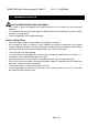
1592022750 Quick reference guide IC 200CX Rel. 1.1 25/05/2009 1 GENERAL ADVICE • • • PLEASE READ BEFORE USING THIS MANUAL This manual is part of the product and should be kept near the instrument for easy and quick reference. The instrument shall not be used for purposes different from those described hereunder. It cannot be used as a safety device. Check the application limits before proceeding. SAFETY PRECAUTIONS • Check the supply voltage is correct before connecting the instrument.
1592022750 Quick reference guide IC 200CX Rel. 1.
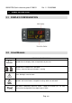
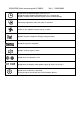
1592022750 Quick reference guide IC 200CX Rel. 1.1 25/05/2009 3 USER INTERFACE 3.1 DISPLAY CONFIGURATION 3.
1592022750 Quick reference guide IC 200CX Rel. 1.
1592022750 Quick reference guide IC 200CX 3.3 Rel. 1.1 25/05/2009 MEANING / FUNCTIONNING OF THE BOTTOM DISPLAY LED Led # 1 – 2 (With RTC) If the bottom display shows the RTC the leds are both blinking. Led # 1 – 2 In function Menu During the time counting to the next defrost for one or both circuits the leds are both blinking. LED during parameters programming In Pr2 level: led #3 indicates the visibility of the parameter; the led #1 and #2 show if the parameter can be modified or not.
1592022750 Quick reference guide IC 200CX Rel. 1.1 25/05/2009 Fig.2 5 DISPLAY INFORMATION 5.1 READ THE SET POINT VALUE Push and release the SET key, the set value is displayed. In stand-by the bottom display shows SetC (set chiller), by pushing SET again the next label is SetH (set heat pump). If the unit is running the only set displayed is related to the running mode. 5.2 1) 2) 3) MODIFY THE SET POINT Push SET key for at least 3 seconds Use the UP or DOWN key to modify the setpoint.
1592022750 Quick reference guide IC 200CX Rel. 1.1 25/05/2009 another time the SET key, the bottom display shows “SEtr” (real setpoint), and the top diplay shows the setpoint that the unit is really using for the thermoregulation. 5.4 KEY KEY FUNCTION ACTION Push and release FUNCTION Show chiller set point SetC and heat pump SetH In chiller or heat pump if the Energy saving or the Push once again Dynamic setpoint are enabled it shows the real setpoint Setr, the led is blinking.
1592022750 Quick reference guide IC 200CX To turn ON or turn OFF the controller (in chiller or heat pump depending from CF51 parameter) Push once Push once Push for 3 seconds Pushing once during programming 5.5 Rel. 1.
92022750 Quick reference guide IC 200CX Rel. 1.1 25/05/2009 7 FIRST INSTALLING 7.1 ON BOARD CLOCK (OPTIONAL) Giving power supply the bottom display shows “rtC” alternated to a temperature or pressure value: It is necessary to set the RTC (Real time clock). ATTENTION The RTC function is an option and it is not possible to update the instrument It is necessary to order the instrument already complete of this features.
1592022750 Quick reference guide IC 200CX Rel. 1.1 25/05/2009 8 ANALOG AND DIGITAL OUTPUT CONFIGURATION 8.1 ANALOG INPUT PB1 - PB2 – PB5 – PB6 Parameters involved: CF08 = Configuration PB1 CF09 = Configuration PB2 CF12 = Configuration PB5 CF13 = Configuration PB6 0. 1. 2. 3. 4. 5. 6. 7. 8. 9. 10. 11. 12. 13. 14. 15. 16. 17. 18.
1592022750 Quick reference guide IC 200CX Rel. 1.
1592022750 Quick reference guide IC 200CX 33. 34. 35. 36. 37. 38. Rel. 1.1 25/05/2009 Thermoregulation request (motocondensing unit) Cooling request (motocondensing unit) Heating request (motocondensing unit) Request step 2 (motocondensing unit) Request step 3 (motocondensing unit) Request step 4 (motocondensing unit) 8.4 DIGITAL OUTPUT (RELAY) CONFIGURATION RL1- RL8 Parameter involved: CF35= Configuration RL1…CF42= Configuration RL8 0. Not enabled 1. Alarm 2. Evaporator water pump / Supply fan 3.
1592022750 Quick reference guide IC 200CX 8.5 Rel. 1.1 25/05/2009 ANALOG OUTPUT CONFIGURATION 0 ÷ 10 VOLT (OUT1 E OUT2) Parametri: CF43 = Analog output OUT1 configuration CF44 = Analog output OUT2 configuration 0 = output disabled 1 = 0..10V output for compressor 1 inverter controlled 2 = 0..10V output for compressor 2 inverter controlled 3 = 0..10V output for auxiliary output 1 4 = 0..10V output for auxiliary output 2 5 = 0..10V output for geothermal function 6 = 0..
1592022750 Quick reference guide IC 200CX Rel. 1.1 25/05/2009 “End” if the programming procedure is completely OK, after 30seconds the regulation starts automatically. “Err” if the programming procedure has found an error and the parameter have not been transferred. In this case turn off and then on the instrument supply to repeat the operation or remove the hot key, with power supply off, to restart the regulation. 9.2 UPLOAD: HOW TO PROGRAM A “HOT KEY” WITH THE PARAMETERS OF THE INSTRUMENT 1.
1592022750 Quick reference guide IC 200CX Rel. 1.1 25/05/2009 Starting from the Pr2 level push the UP key for 2 seconds and the bottom display will show Pr3. The top display still shows PAS. After selecting the level push the SET key and the top display will show the 0 blinking value where to insert the password. Set the password level using the UP and DOWN keys then confirm with SET key.
1592022750 Quick reference guide IC 200CX Rel. 1.1 25/05/2009 Remember that it is necessary to know the old password value. 1. Enter the Pr3 level 2. Select a parameter family. 3. Select the “Pr3” on the bottom display; the current password value on the top display. Push the SET key to change the value that now is blinking. 4. Use the UP or DOWN key to insert the NEW PASSWORD value, then push SET to confirm the new value. 5. The top display blinks for some seconds and then shows the next parameter 6.
1592022750 Quick reference guide IC 200CX Rel. 1.1 25/05/2009 4. 5. Select a parameter family with DOWN or UP keys. Push SET to enter, the bottom display shows the first available parameter label while the top display shows its value. The user can shows and modify all the paramters belonging to this family. Parameter status, leds and bottom display in Pr2 Leds 1 / 2 are blinking: the parameter can not be changed. All the leds are off: the parameter ca not be seen in Pr1 level.
1592022750 Quick reference guide IC 200CX Rel. 1.1 25/05/2009 Leds 1 / 2 are blinking: the parameter can not be changed in Pr1 and Pr2 level. All the leds are off: the parameter is available only in Pr3. Led 4 on: the parameter can be changed also in Pr2. Led 4 blinking: the parameter is visible but not modifiable in Pr2. Leds 3 / 4 on: the parameter is visible and modifiable in Pr2 and in Pr1. Leds 3 / 4 blinking: the parameter is visible but not modifiable in Pr1 and in Pr2.
1592022750 Quick reference guide IC 200CX 3) 4) 5) 6) Rel. 1.1 25/05/2009 Bottom display: alarm label code. Top display: label rSt to reset or NO if it is not possible. Use the UP or DOWN to scroll the alarm list. Pushing SET when the rSt label is displayed the corresponding alarm will be reset, then the display shows next alarm in the list, pushing SET again the alarm is reset and the display shows next alarm etc.
1592022750 Quick reference guide IC 200CX Rel. 1.1 25/05/2009 11.5 ERASE THE ALARM LOG LIST ALOG FUNCTION TO ERASE THE LOG LIST 1. Enter the function Menu. 2. Use the UP or DOWN keys to select ALOG on the bottom display. 3. Push the SET key. 4. Push UP or DOWN keys and search the ArSt label on the bottom display; the top display shows PAS. 5. Push SET: the bottom display shows PAS and the top display shows 0 value blinking. 6. Insert the password 7.
1592022750 Quick reference guide IC 200CX Rel. 1.1 25/05/2009 12 TABLE OF THE OUTPUT STATUS IN ALARM CONDITION The alarm codes are made of letters and numbers to define the different typologies:. 12.
1592022750 Quick reference guide IC200CX Rel. 1.
1592022750 Quick reference guide IC 200CX ACF8 ACF9 AC10 AC11 AEht (1) (2) (3) (4) (5) Configuration alarm Configuration alarm Configuration alarm Configuration alarm High water temperature inlat evaporator Rel. 1.
1592022750 Quick reference guide IC200CX b(n)lP b(n)tF b(n)PH b(n)PL b(n)dF b(n)Cu b(n)Cu b(n)rC b(n)ds b(n)Ac b(n)Ah Rel. 1.
1592022750 Quick reference guide IC 200CX Rel. 1.
1592022750 Quick reference guide IC 200CX Pr3 Rel. 1.
1592022750 Quick reference guide IC 200CX CF 6 Rel. 1.1 25/05/2009 Number of capacity steps 0= none 1= 1 2= 2 3= 3 CF 14 Analog Inputs Pressure or temperature analogue input functioning 0 = Temperature / pressure NTC – 4÷20 mA : The condensing temperature is controlled with NTC probe while for the evaporating pressures of the circuits 1 and 2 and the pressure probe configured as auxiliary output 1 and 2 are controlled with 4÷20mA transducers.
1592022750 Quick reference guide IC 200CX CF 22 Pressure value at 4mA or 0.5 Vdc of the PB4 transducer CF 23 Pressure value at 20mA or 5 Vdc of the PB4 transducer CF 24 CF 25 CF 26 CF 27 CF 28 CF 29 CF 30 CF 31 CF 32 CF 33 CF 34 CF 35 CF 36 CF 37 CF 38 CF 39 CF 40 CF 41 CF 42 Configuration of RL1 Configuration of RL2 Configuration of RL3 Configuration of RL4 Configuration of RL5 Configuration of RL6 Configuration of RL7 Configuration of RL8 Rel. 1.1 25/05/2009 0 -14 0 -14 50.0 725 50.
1592022750 Quick reference guide IC 200CX CF 45 CF 49 OUT 3 configuration 0= Not enabled 1= 0..10V signal for compressor 1 inverter controlled 2= 0..10V signal for compressor 2 inverter controlled 3= 0..10V signal for auxiliary output 1 4= 0..10V signal for auxiliary output 1 5= 0..10V signal for geothermal function 6= 0..10V signal for condenser fan circuit 1 7= 0..10V signal for condenser fan circuit 2 8= PWM signal for condenser fan circuit 1 9= PWM signal for condenser fan circuit 2 o1 ..
1592022750 Quick reference guide IC 200CX CF 54 CF 55 CF 56 CF 57 CF 58 Pr1 Pr2 Pr3 Param eters Sd 1 Rel. 1.
1592022750 Quick reference guide IC 200CX ES 10 Rel. 1.
1592022750 Quick reference guide IC 200CX CO 11 CO 12 CO 13 CO 14 CO 15 CO 16 CO 17 CO 18 CO 19 Rel. 1.1 25/05/2009 Part - winding start-up time.
1592022750 Quick reference guide IC 200CX CO 20 Rel. 1.1 25/05/2009 CO 31 Operative mode of the condenser pump 0= Not enabled 1= ON/OFF: continuous operation type 1 When the unit is running in Chiller or Heat Pump the pump is running. In std-by or remote OFF mode, the pump is OFF. 2= ON/OFF: on if called by compressor When a compressor is running, the pump is running. 3= ON/OFF: continuous operation type 2 When the unit is running in Chiller or Heat Pump or in STD-By or in OFF, the pump is running.
1592022750 Quick reference guide IC 200CX CO 37 Rel. 1.1 25/05/2009 CO 48 Maximum unloading duration time to keep activated the Unloading function from high temperature of the evaporator water inlet (See unloading function). Unloading compressor setpoint in chiller to prevent low temperature of the evaporator water inlet (See unloading function). Unloading Differential to prevent low temperature of the evaporator water inlet (See unloading function).
1592022750 Quick reference guide IC 200CX CO 61 CO 62 CO 63 CO 64 CO 65 Rel. 1.
1592022750 Quick reference guide IC 200CX CO 83 Rel. 1.1 25/05/2009 CO 85 Probe selection (Pb1..Pb6) for modulating condenser water pump in chiller Probe selection (Pb1..
1592022750 Quick reference guide IC 200CX US 6 Rel. 1.1 25/05/2009 US 7 Probe selection for for auxiliary relay 2 control. Allows to select which probe value Pb1..
1592022750 Quick reference guide IC 200CX Rel. 1.1 25/05/2009 US 22 Temperature to activate geothermal function US 23 Differential to deactivate geothermal function US 24 Time to activate/deactivate geothermal function US 25 US 26 US 27 US 28 Probe 1 selection (Pb1..Pb6) for geothermal function Probe 2 selection (Pb1..
1592022750 Quick reference guide IC 200CX FA 8 FA 9 FA 10 FA 11 FA 12 FA 13 FA 14 FA 15 FA 16 FA 17 FA 18 FA 19 FA 20 Rel. 1.1 25/05/2009 Maximum speed for condenser fan in Chiller mode. To set the maximim fan speed percentage value (30..100%), it is related to the fan power supply.
1592022750 Quick reference guide IC 200CX FA 21 FA 22 FA 23 Rel. 1.1 25/05/2009 Proportional speed control FA01 = 4 CUT-OFF differential in heat pump. To set a temperature/pressure differential to stop the fan. ON/OFF regulation FA01 = 2/3 Differential step circuit n° 2 Over ride CUT- OFF in Heat pump. To set a temperature/pressure differential to keep the minimum fan speed. 0.1 1 0.0 0 25.0 45 14.0 203 °C °F Bar Psi Dec int Dec int 0.1 1 0.0 0 25.0 45 14.
1592022750 Quick reference guide IC 200CX Ar 7 Rel. 1.1 25/05/2009 Ar 12 Probe selection for antifreeze heaters / integration heating in Heat Pump mode 0= Not enabled 1= Evaporator inlet. 2= Evaporator outlet 1 and 2. 3= Evaporator outlet 1 and 2 and common outlet. Thermoregulation probe for anti-freeze / condenser heaters. 0= not enabled. 1= Condenser common water inlet probe. 2= Condenser common water inlet and condenser inlet 1 / 2 probe. 3= Condenser water outlet 1 / 2 probe.
1592022750 Quick reference guide IC 200CX Pr1 Pr2 Pr3 Password Password Password Param eter dF 1 Description Rel. 1.1 25/05/2009 0 0 0 999 999 999 min max Defrost dF 2 Defrost configuration: 0= Not enabled 1= Temperature / pressure 2= start depends on par. dF24 stop for time duration 3= start depends on par.
1592022750 Quick reference guide IC 200CX dF 21 dF 22 dF 23 Param eters dF 24 dF 25 dF 26 dF 27 dF 28 Pr1 Pr2 Pr3 Param eters AL 1 AL 2 AL 3 Rel. 1.
1592022750 Quick reference guide IC 200CX Rel. 1.1 25/05/2009 AL 4 Low pressure alarm differential from analogue input AL 5 AL 9 Maximum number of low pressure events from digital/analogue inputs: Always manual reset if AL05 = 0 Always automatic reset if AL05 =16 From automatic to manual reset if AL05= 1..
1592022750 Quick reference guide IC 200CX AL 23 Rel. 1.1 25/05/2009 AL 31 “Evaporator flow switch / supply fan overload” deactivation time to reset the alarm Compressor overload alarm Compressor overload alarm delay after compressor start-up Maximum number of compressor overload alarm per hour Always manual reset if AL20 = 0 Always automatic reset if AL20 =16 From automatic to manual reset if AL20 =1..
1592022750 Quick reference guide IC 200CX AL 38 Rel. 1.
1592022750 Quick reference guide IC 200CX AL 51 AL 52 AL 53 AL 54 AL 55 AL 56 AL 57 AL 58 AL 59 AL 60 AL 61 AL 62 AL 63 AL 64 AL 65 AL 66 Rel. 1.1 25/05/2009 Number of compressor high discharge temperature events per hour to determine the alarm reset condition: Always manual reset if AL51 = 0 0 Always automatic reset if AL51 =16 From automatic to manual if AL51 = 1..
1592022750 Quick reference guide IC 200CX AL 67 Rel. 1.1 25/05/2009 AL 68 AL 69 Maximum number of low water temperature alarm events Always manual reset if AL67 = 0 Always automatic reset if AL67 =16 From automatic to manual reset if AL67 =1..
1592022750 Quick reference guide IC 200CX Rel. 1.1 25/05/2009 15 WIRING CONNECTIONS 15.1 HARDWARE RESOURCES FOR IC206CX MODEL 6 digital outputs (relays) MAX current on the relay contacts relè 5(2)A 250V - MAX common current 10A 250V 11 digital inputs (free of voltage) 6 analogue inputs: • 4 NTC / PTC probes • 2 NTC / PTC / pressure transducer 4÷20 mA / pressure transducer ratio-metric 0÷ 5.0 Volt 4 modulating outputs: • 2 configurable 0 ÷ 10 Volt • 2 configurable 0 ÷ 10.
1592022750 Quick reference guide IC 200CX Rel. 1.1 25/05/2009 16 INSTALLING AND MOUNTING 16.1 PANEL CUT- OUT The instrument must be mounted on vertical panel, with panel cut-out 71x29mm, and fixed using the special bracket supplied. Avoid locations subject to heavy vibration, corrosive gases or excessive dirt. Ensure ventilation around the instrument. 16.2 VERTICAL BOARDS VI620CX PANEL CUT-OUT The remote terminals are for panel mounting, panel cut-out 72x56 mm, and screwed with two screws.
1592022750 Quick reference guide IC 200CX Rel. 1.1 25/05/2009 WALL MOUNTING: use the vertical V-KIT (black, white and grey) as described in the following scheme: 17 ELECTRICAL CONNECTIONS The instrument is provided with: • 2 removable terminal blocks MOLEX MICROFIT 14 and 18 ways for power supplay / digital and analogue inputs and modulating outputs • 1 removable terminal blocks AMP 12 ways for the relay outputs • 5 ways connector for TTL RS485 interface outputs.
1592022750 Quick reference guide IC 200CX Rel. 1.1 25/05/2009 • signal cable AWG 24 • power supply cable AWG 22 • relay output AWG 17 General notes: • Check the connecitons and the line voltage before turning on the power supply. • Keep low voltage cables, such as analogue/digital inputs/outputs and probes, away from power cables and terminals. • Respect the maximum load current of each relay output, in case of power loads use filtered contactors. 18 TECHNICAL DATA Housing: self extinguishing ABS.