Section 5 100 Ton Ram Operating Instructions for Cam & Groove Holedall Couplings Cam & Groove Holedall Couplings Dixon Valve & Coupling Company 800 High Street • Chestertown, MD 21620 ph: 800•355•1991 fax: 800•283•4966 www.dixonvalve.
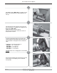
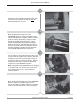
100 Ton Ram Instruction Manual 1 Install Main Pusher (M011-065) on cylinder rod cap. Make sure that the pusher is fully installed on the rod cap. 2 Install the Cam & Groove pusher necessary to do the size and style of coupling to be swaged into the Main Pusher (M011-065). Additional pushers may be required. Reference the chart at the end of this section for proper pusher selection. 3a Install the required die holders ensuring that the seams between the die holder halves do not line up.
100 Ton Ram Instruction Manual 4 Accurately measure the hose O.D. with a diameter tape. Each end of the hose should be measured to guarantee the correct ferrule and die selection. Select the correct ferrule and die based upon the hose free O.D. just measured from the die chart. Make sure that the hose end is cut square. If the hose is to be static grounded, follow hose manufacturers procedure for proper static grounding.
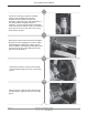
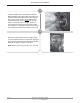
100 Ton Ram Instruction Manual 8 Cut the hose end square and if the assembly requires static grounding, follow the hose manufacturer’s procedure for proper static grounding. Lubricate the hose I.D. and the O.D. of the stem with Dixon Coupling Lubricant or equivalent. Insert the Cam and Groove fitting with ferrule onto the hose until the ferrule is even with the mark closest to the hose end. This is the second mark made on the hose. 9 Bring the hose with the stem and ferrule through the die bed.
100 Ton Ram Instruction Manual 11a Lifting up the hose, insert one die half under the hose. Lower the hose so that it rests on the die. Insert the other die half. Make sure that the seams of the die do not line up with the seams on the die holders. 11b While holding the die in place with one hand, place one of the tie down bars over the die so that it does not come out of the die holder unexpectedly. Secure the tie down bar by tightening the bolt. For style "C" couplings go to step 12.
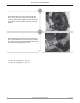
100 Ton Ram Instruction Manual For “C” style couplings requiring spacer rings: 12a Release both cam arms. 12b Remove the gasket from the coupler. 12c Put the spacer rings between the ferrule and coupler head, making sure that the two ringhalves meet over the turned over portion of the ferrule. 12d Insert the proper pusher into the coupler (reference the chart at the end of this section for proper pusher selection).
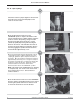
100 Ton Ram Instruction Manual 12e Check the ferrule engagement with the stem collar. The mark on the ferrule (from Step 6a) must be positioned under the cam arm. 12f Move the directional control lever to the “FORWARD” position. Depress the button on the remote and advance the cylinder until the end of the ferrule is near the die opening. Using a wooden board or metal pipe, lift the ferrule up. Jog the cylinder by quickly depressing and releasing the button on the remote.
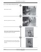
100 Ton Ram Instruction Manual 12i Position a rubber sheet or pad under the die bed. While holding the die in place with one hand, loosen the bolt on the tie down bar and move the tie down bar so that it clears the die. Slowly slide the hose towards the pusher. When the die clears the die holder, one or both halves may fall to the floor. If one half remains on the ferrule, tap it with a mallet until it releases. If both halves remain on the ferrule, it may require the halves be pried apart at the seam.
0 Ton Ram Instruction Manual For “E” style couplings: 13a Check the ferrule for proper alignment. Ensure that the mark on the ferrule (from Step 6b) is in the center of the stem collar. 13b Move the directional control lever to the “FORWARD” position. Depress the button on the remote and advance the cylinder until the end of the ferrule is near the die opening. Using a wooden board or metal pipe, lift the ferrule up. Jog the cylinder by quickly depressing and releasing the button on the remote.
100 Ton Ram Instruction Manual 13e Position a rubber sheet or pad under the die bed. While holding the die in place with one hand, loosen the bolt on the tie down bar and move the tie down bar so that it clears the die. Slowly slide the hose towards the pusher . When the die clears the die holder, one or both halves may fall to the floor. If one half remains on the ferrule, tap it with a mallet until it releases.
100 Ton Ram Instruction Manual Pushers and Spacer Rings For Cam & Groove Size Description Part Number 1” Type “E” Pusher Type “C” Pusher 100PUSHGCRC 100PUSHCGRC 1 1/2” Type “E” Pusher Type “C” Pusher Spacer Ring 100PUSHCG15E 100PUSHCG15 (2 pieces) 150CGSPACE 2” Type “E” Pusher Type “C” Pusher 100PUSHCE2 100PUSHCG2 3” Type “E” Pusher Type “C” Pusher 100PUSHCG3 100PUSHCG2 4” Type “E” Pusher Type “C” Pusher 100PUSHCG4E 100PUSHCG4C Note: Spacer Rings are to be used with Type “C” Couplings ON