25 Ton Ram Operating Instructions Section 4 External Swaging of Cam & Groove Dixon Valve & Coupling Company 800 High Street • Chestertown, MD 21620 ph: 800•355•1991 fax: 800•283•4966 www.dixonvalve.
5 Ton Ram Instruction Manual Externally Swaged Cam & Groove 1 Before you begin, make sure the ram is fully retracted, and remove the 25PUSH400 (also referred to as the pusher hat) from the main pusher plate, if installed on the ram. 2 Insert Die Holders into the Die Bed Plate as follows: a) DH9-004 - Master Die Holder to hold all of the other die holders. b) DH9-004-1 - Die Holder for 4” I.D. hoses only. c) DH6-003 - Die Holder for 1 1/4” - 3” I.D. hose dies (fits into DH9-004).
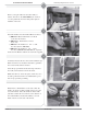
25 Ton Ram Instruction Manual Externally Swaged Cam & Groove 5a Note : When using the Notched Stem and ferrule system these guidelines must be followed: A. Before stem insertion, assemble the ferrule onto the stem by sliding the turned over portion of the ferrule past the notched sections of the stem collar. Rotate the ferrule 90° (1/4 turn). B. Before starting the swaging process, make sure that the turned over portion of the ferrule and the collar are fully engaged. C.
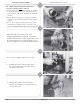
25 Ton Ram Instruction Manual Externally Swaged Cam & Groove 6c c. Release the cam arms. 6d d. Remove the gasket from the coupler. 6e 6f e. Bring the hose and coupling assembly up through the base of the die bed. Note: One or both cam arms may close going through the die bed. If this happens, release the cam arms. f. Put the selected die into the die bed. 6g g.
25 Ton Ram Instruction Manual Externally Swaged Cam & Groove 6h h. Insert the proper pusher into the coupler (reference the chart at the end of this section for proper pusher selection). 6i 6j i. j. Bring the assembly down into the opening of the die. Jog the ram cylinder down until it meets the pusher. Note: Check spacer rings for proper positioning. 6k k. Hold the “on” button down (or depress the foot pedal) and continue the swage process until the spacer rings begin to enter the die.
25 Ton Ram Instruction Manual Externally Swaged Cam & Groove 6end For “C” Style couplings not requiring spacer rings, perform Steps 6a through 6f and 6h through 6n. Step 6k hold the “on” button down (or depress the foot pedal) and continue the swage process until the top of the ferrule has passed the top of the dies. Don’t let the locking ear on the coupler touch the die. 7a For “E” Style couplings follow steps 1-5 then: a.
25 Ton Ram Instruction Manual Externally Swaged Cam & Groove 7e-f e. Install the proper pusher over the adapter (reference the chart at the end of this section for proper pusher selection). f. Bring the assembly down into the opening of the die. 7g g. Jog the ram cylinder down until it meets the pusher. Make sure that the cylinder plate contacts the pusher flush. 7h h.
25 Ton Ram Instruction Manual Externally Swaged Cam & Groove Pushers and Spacer Rings For Cam & Groove Size Description Part Number 1” Type “E” Pusher Type “C” Pusher Spacer Ring RE100PUSH RC100PUSH 100CGSPACE 1 1/2” Type “E” Pusher Type “C” Pusher Spacer Ring RE150PUSH RC150PUSH (2 pieces) 150CGSPACE 2” Type “E” Pusher Type “C” Pusher Spacer Ring D011-018 D011-018 200CGSPACE 3” Type “E” Pusher Type “C” Pusher Spacer Ring 25PUSH300E D011-018 300CGSPACE 4” Type “E” Pusher Type “C” Pusher Sp