Operator's Manual 4000 SERIES ZTR® MOWERS 2001
IMPORTANT: READ CAREFULLY The Dixon® ZTR® Mower is both easy and fun to operate. However, any power mower must be operated properly to be safe. It is not a toy or a recreational vehicle. Before you start to use the mower: read the operator's manual carefully, and become completely familiar with the controls. The information in this operator's manual applies to all Dixon® ZTR® 4000 Series Model Mowers. Your Dixon dealer will gladly answer any questions.
INDEX SAFETY ............................................................ Pages WARRANTY POLICY ...................................... Page SPECIFICATIONS ........................................... Page SEAT ADJUSTMENT ...................................... Page CONTROLS ..................................................... Pages OPERATION INSTRUCTIONS ...................... Pages CARE AND MAINTENANCE ......................... Pages STANDARD PARTS LIST ................................
SAFETY RIDING LAWNMOWERS, IF IMPROPERLY OPERATED, CAN CAUSE SERIOUS INJURY OR DEATH The most common causes of injury to the operator or bystander... BLADE CONTACT TIP-OVER RUN-OVER BACK-OVER ...read and understand this manual to prevent injuries.
SAFETY SAFETY SYMBOLS Safety Alert Symbol When you see this symbol, BE ALERT to the potential for injury. Follow recommended safety precautions and safe operating practices. Danger indicates an imminently hazardous situation which, if not avoided, will result in death or serious injury. Warning indicates a potentially hazardous situation which, if not avoided, could result in death or serious injury.
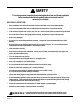
SAFETY This cutting mower is capable of amputating hands & feet, and throwing objects. Failure to observe the following safety instructions could result in serious injury or death. GENERAL OPERATION: • Read, understand, and follow all instructions in the manual and on the mower before starting. • Only allow responsible adults, who are familiar with the instructions, to operate the mower. • Clear the area of objects such as rocks, toys, wire, etc., which could be picked up and thrown by the blade.
SAFETY SLOPE OPERATION: Slopes are a major factor related to loss-of-control and tip-over accidents, which can result in severe injury or death. All slopes require extra caution. If you cannot back up the slope or if you feel uneasy on it, do not mow it! DO Mow across the slope with your Dixon ZTR - never up or down. Remove obstacles such as rocks, tree limbs, etc. Watch for holes, ruts or bumps. Uneven terrain could overturn the mower. Tall grass can hide obstacles. Use slow speed.
SAFETY CHILDREN: Tragic accidents can occur if the operator is not alert to the presence of children. Children are attracted to lawn mowers and the mowing activity. NEVER assume children will stay where they were last seen. Be alert to avoid accidents. • Keep children out of the mowing area and under the watchful care of another responsible adult. • Be alert and turn mower off if a child enters the area. • Before and during backing, look behind and DOWN for small children. • Never carry children.
SAFETY SERVICE: • Use extra care in handling gasoline and other fuels. They are flammable and vapors are explosive. Use only an approved container. Never remove gas cap or add fuel with the engine running. Allow engine to cool before refueling. Do not smoke. Never refuel the mower indoors. Never store the mower or fuel container inside a building where there is an open flame, If fuel is spilled on clothing, change clothing immediatley.
DIXON INDUSTRIES, INC. a BLOUNT company AIRPORT INDUSTRIAL PARK PO BOX 1569 COFFEYVILLE KS 67337 0945 316 251 2000 FAX 316 251 4117 DIXON LIMITED WARRANTY POLICY - 3000 & 4000 SERIES WARRANTY: Home Owner Application: This Dixon Warranty term is for a period of two (2) years from date of purchase. Commercial Application: Dixon mowers used for commercial application are warranted for 30 days from the date of purchase.
SPECIFICATIONS Models ZTR 4423 CHASSIS: Twin 12 gauge side frames and 7 gauge transmission and engine base plate. BODY: All body parts are made of high density polyethylene. Dent and corrosion resistant. Front body contains access panel for battery service. MOWER DECK: 13 GA stamped steel construction. (3) blades combine for a 42" cut width. Cut height approximately 1" to 4" via 7 position lift handle. BLADE DRIVE: Electric clutch.
SEAT ADJUSTMENT INSTRUCTIONS 1. Place parking brake in ON position. (Pull brake lever up) 2. Raise and push seat assembly forward. 3. Loosen five nuts, P/N 3205, and slide seat forward or backward to desired position. Retighten nuts, P/N 3205. DO NOT operate mower without seat adjustments properly tightened. 4 Raise and push seat assembly and upper body rearward to closed position.
CONTROLS The Dixon ZTR has a unique transaxle that requires only two drive levers to control braking, turning, speed, and direction. On initial operation, set throttle speed on slow. Operate with mower blade "OFF". To avoid "over-controlling" the mower, use a light touch on the drive levers. Slight movements using fingertip control is all that is necessary. PARKING BRAKE: The parking brake is designed to hold the mower from moving and is not intended for use in stopping the mower while it is in motion.
CONTROLS Neutral Slow Forward Fast Forward 90° Right Turn (Left turn opposite) Slow Reverse TO GO FORWARD: From neutral position, gently push both drive levers forward. To increase speed, move levers farther forward. TO GO BACKWARD: From neutral position, gently pull both drive levers toward you. TURNING: Turning is controlled by moving one drive lever slightly forward or rearward of the other. To turn left, move left lever rearward of the right lever.
CONTROLS BLADE DRIVE: Located on control panel, on operator's right. To engage the mower blades, pull up on the switch. To disengage blades, push down. CIRCUIT BREAKER: Protection of the electrical system is by (1) 15 amp circuit breaker. If circuit breaker trips, push button to reset. If this condition repeats, consult dealer for inspection and repair. MOWER DECK CUT HEIGHT LIFT LEVER: Located to the left of operator. Controls the cutting height. Seven positions of adjustment.
OPERATION INSTRUCTIONS Safe and successful operation will depend upon the operator having the correct knowledge of all controls used on the mower and making good judgements about the terrain to be mowed. NEVER allow anyone to operate the mower without complete knowledge of all controls and their functions. During initial operation, "learning to drive", set throttle at slow speed. Sound judgement by the operator will prevent accidents.
OPERATION INSTRUCTIONS TESTING OF SAFETY INTERLOCK SYSTEMS: PARKING BRAKE SWITCH TEST: a)Place Parking Brake in OFF position b)Turn ignition switch to START Engine should not turn over or attempt to start. BLADE DRIVE SWITCH TEST: a)Place Parking Brake in ON position b)Engage blade drive switch c)Turn ignition switch to START Engine should not turn over or attempt to start.
OPERATION INSTRUCTIONS STARTING INSTRUCTIONS: 1. Parking brake must be on, and blade drive disengaged. 2. Move throttle control to "Choke" position if engine is cold, full throttle if warm. 3. Insert ignition key and turn to "Start" position. When engine starts, release ignition key. Key will return to "Run" position. 4. Move throttle from "Choke" to desired speed position. 5. Release parking brake. 6. Operate the mower per the "Control" instructions on page 14.
OPERATION INSTRUCTIONS MOWING WITH A MULCHING ATTACHMENT: Mulching or recycling the grass clippings requires a totally different mowing approach than would be normal when side discharging or bagging the grass. There may be instances or conditions where it is not possible to hide all of the recycled or mulched clippings. In order to achieve the best results, please read and follow the mulching tips listed below: 1. Set the engine speed control to the wide open or full setting. 2.
OPERATION INSTRUCTIONS MOWING WITH A GRASS CATCHER ATTACHMENT: In order to achieve optimum performance when mowing with a grass catching attachment, please read and follow the tips listed below. 1. Some applications may require installation of an optional weight box on the front of the mower to offset cut grass weight. 2. Set engine speed control to the wide open or full setting. 3. Do Not Attempt To Cut Grass When It Is Wet. Wet grass will clog both the underside of the deck and the attachment chutes.
OPERATION INSTRUCTIONS SIDE DISCHARGE OF THE CLIPPINGS: In order to achieve optimum performance when side discharging the grass clippings, please read and follow the tips listed below. Additional information can be found in the troubleshooting guide. CAUTION Be sure that deflector is properly installed on the discharge chute. 1. Set engine speed control to the wide open or full setting. 2. Do Not Attempt To Cut Grass When It Is Wet. Wet grass will clog the underside of the deck and discharge area. 3.
CARE AND MAINTENANCE This portion of the owners manual deals with normal service items which can be performed by the owner. Please remember that if you are in doubt as to the correct service procedures to be followed, these and other service situations can be handled by a Dixon ZTR dealer who is familiar with the service of your mower. MAINTENANCE SCHEDULE: To insure a long and trouble free service life of all components, a regular and thorough maintenance schedule should be followed.
CARE AND MAINTENANCE CUTTER BLADE MAINTENANCE: NOTE: Observe proper blade position prior to removal. 1. Safely raise front of mower. 2. Hold or block blade from turning. 3. Loosen blade nut and remove blade. 4. When replacing blade, tighten blade nut securely. Refer to diagram. CAUTION Wear heavy, thick gloves when holding onto cutter blade. Avoid touching the sharp edge of the blade. NOTE: BE SURE BLADE IS CENTERED ON PILOT BEFORE TIGHTENING NUT TO 60 FT. LBS. TORQUE.
CARE AND MAINTENANCE BELT TENSION TRANSAXLE DRIVE BELT: P/N 7650 No adjustment required. ENGINE TO MOWER DECK BELT: P/N 7725 No adjustment required. Correct belt tension is maintained through a fixed engine location and a spring loaded idler system. A pulsing movement of the belt idler will be observed both during engagement of the electric blade clutch and actual operation of the mower deck.
CARE AND MAINTENANCE MOWER DECK LEVELING PROCEDURE: 1. Place mower on a smooth, level surface and check tire pressures to insure correct stance. Tires should be inflated as follows: Front: 16 - 21 lbs Rear: 8 - 14 lbs 2. Turn each outer blade tip to align with the deck in a side to side manner. 3. Measure from the floor surface up to the bottom of the blade tip on the discharge side of the mower. Retain this measurement. Move to the opposite side and check to see if that measurement is the same.
CARE AND MAINTENANCE DECK REMOVAL: 1. Place cut height lever in lowest cut position. 2. Pull belt idler back to allow belt to be removed from idler pulley and electric clutch pulley. 3. Remove hair pin cotter and washer from one end of deck support cross shaft. Note location of remaining shim washers used between chassis and mower deck plates. Slide shaft from chassis and mower deck. 4. Remove hair pin cotter and washer from each deck L-rod. Remove L-rods from lift arms. At this point, deck will drop down.
CARE AND MAINTENANCE CAUTION HOT oil may cause burns. Allow engine to cool before draining oil. CHANGING THE ENGINE OIL: 1. The "Dapco" oil drain valve is located on the left side of the engine crankcase. 2. Place a suitable container under the drain valve. The fitting of a short piece of hose will help direct the oil. 3. To drain turn hex head valve stem counter clockwise with 10mm wrench or socket. Open to full open (approximately 7 turns). 4. After engine is drained tighten hex stem..
CARE AND MAINTENANCE LUBRICATION: CHASSIS: Number of grease zerks used: (7) LOCATIONS: (1) each front wheel caster and each front wheel hub. (1) each mower deck SERVICE INTERVALS: Every 50 hours of operation. RECOMMENDED GREASE: Name brand wheel bearing or multi-purpose grease. Once per season or every 50 hours of operation (3 pumps each). Lubrication of the mower deck hubs will help dispel moisture within the hub casting. Bearings are of a sealed variety.
CARE AND MAINTENANCE DRIVE SYSTEM ADJUSTMENTS: Due to both the complex nature of the transmission and the number of special tools required for service, adjustments should be entrusted to your dealer. There are a number of simple owner service items which greatly influence the performance of the drive system. 1. Front and rear tires must be inflated to proper specifications. 2. Rear drive chain tension. 3. Tightness of all controls and linkages pertaining to the drive levers. 4.
CARE AND MAINTENANCE WHEELS AND TIRES: Correct tire pressure is important for correct operation of mower. Front Tires Rear Tires 11 X 4.00 X 5 18 X 9.50 X 8 16-21 lbs. PSI 8-14 lbs. PSI NOTE: Check lug nuts periodically for tightness. ELECTRICAL SYSTEMS: Keep all connections clean and tight. CLEANING THE MOWER: Wash mower periodically. Clean above and below deck. NOTE: Allow mower to cool before washing. If bearings are hot, they will draw moisture inside as they dry and cause corrosion.
STANDARD SERVICE PARTS LIST BLADES: Lo-Lift: Standard Hi-Lift: P/N 6236 P/N 8688 BELTS: Engine To Mower Deck: Serpentine Belt: Engine To Transmission: P/N 7725 P/N 6109 P/N 2497 BRIGGS & STRATTON FILTER PART NUMBERS: Please refer to Briggs & Stratton Engine Operators Manual for correct service intervals for engine oil changes and air filter maintenance. Protect your engine investment, use only original equipment filters.
TROUBLESHOOTING MOWER CUT QUALITY: There are many variables that can effect the cut quality of any riding mower. Type and conditions of grass, cut height setting, engine RPM and ground speed are some of the variables that interact creating differences in cut quality. Examination of one or more of the above will generally produce a quality cut. The Troubleshooting Chart suggests practices and adjustments that may be helpful in improving cut quality.
TROUBLESHOOTING DRIVE SYSTEM: SITUATION CAUSES REMEDY Mower pulls to one side or the other Drive adjustment Consult your dealer for repair Poor driving performance Operation of mower Review operators section of owners manual Page 33
TROUBLESHOOTING ELECTRICAL SYSTEM: SITUATION CAUSES REMEDY Starter will not turn engine over Circuit breaker disengaged Push button to reset Consult your dealer for repair Starter will not turn engine over Dead Battery Charge battery Battery discharge Poor connections on battery Tighten or replace as required Battery water low Wrong battery installed in mower Battery discharge Engine electrical system not functioning correctly Have electrical system checked by your dealer Battery discharge
OWNER INFORMATION DIXON INDUSTRIES, INC. A BLOUNT International Inc. Co.
engine exhaust from this product contains chemicals known to the State of California WARNING: The to cause cancer, birth defects or other reproductive harm. Dixon® and ZTR® are registered trademarks of Dixon Industries, Inc. DIXON INDUSTRIES, INC. A BLOUNT International Inc. Co. PO BOX 1569 COFFEYVILLE KS 67337 0945 316 251 2000 4000 Series 4423 Part No.