SILVERTIP™ ZTR® Safety Instructions & Operator’s Manual
IMPORTANT - READ CAREFULLY The Dixon® ZTR® mower is both easy and fun to operate. However, any power mower must be operated properly to be safe. It is not a toy or a recreational vehicle. Before you start to use the mower, read this Operator’s Manual carefully. It contains valuable information that is necessary for the safe operation of the machine. Observe all safety rules and become completely familiar with the controls.
TABLE OF CONTENTS Page SAFETY & WARNING....................................4 -15 WARRANTY.........................................................16 SPECIFICATIONS..............................................17 CONTROLS..................................................18-21 OPERATION INSTRUCTIONS....................22-32 CARE & MAINTENANCE............................33-49 TROUBLESHOOTING..................................50-51 STANDARD SERVICE PARTS LIST...............
SAFETY RIDING LAWN MOWERS, IF IMPROPERLY OPERATED CAN CAUSE SERIOUS INJURY OR DEATH Pictured below are the most common causes of injury to the operator or bystander. Please read and understand this manual to prevent injuries.
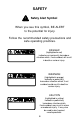
SAFETY Safety Alert Symbol When you see this symbol, BE ALERT to the potential for injury. Follow the recommended safety precautions and safe operating practices. DANGER (highlighted in red) indicates an imminently hazardous situation which, if not avoided, will result in death or serious injury. WARNING (highlighted in orange) indicates a potentially hazardous situation which, if not avoided, could result in death or serious injury.
WARNING Failure to observe the following safety instructions could result in serious injury or death. GENERAL OPERATION: Read, understand, and follow all instructions in this manual and on the mower before starting. Only allow responsible adults, who are familiar with the instructions, to operate the mower. Clear the area of objects such as rocks, toys, wire, etc., which could be picked up and thrown by the blade. Be sure the area is clear of other people before mowing.
WARNING Failure to observe the following safety instructions could result in serious injury or death. GENERAL OPERATION (continued): Never leave a running mower unattended. Always turn off blades, set parking brake, stop engine and remove key before dismounting. Turn off blades when not mowing. Injury could occur from contact with moving parts. Under no circumstances should you place hands or feet under the mower deck or in the chute while blades or impeller are still running.
WARNING Failure to observe the following safety instructions could result in serious injury or death. GENERAL OPERATION (continued): Never dismount mower without applying parking brake or stopping engine. Protect your eyes. Always wear safety goggles or safety glasses with side shields when operating mower. Data indicates that operators, age 60 years and above, are involved in a large percentage of riding mowerrelated injuries.
WARNING Failure to observe the following safety instructions could result in serious injury or death. SLOPE OPERATION: Slopes are a major factor related to loss-of-control and tip-over accidents, which can result in severe injury or death. All slopes require extra caution. If you feel uneasy on a slope, do not mow it! DO Mow across the slope with your Dixon® ZTR® -never up or down. This will decrease the risk of tip-over.
WARNING Failure to observe the following safety instructions could result in serious injury or death. SLOPE OPERATION (continued): DO (continued): Keep all movement on the slopes slow and gradual. Do not make sudden changes in speed or direction. Use extreme caution when operating the mower with attachments to prevent tip-over or roll-over. If front wheels lift off the ground, pull levers back to stabilize the mower. Discontinue mowing the slope! R.O.P.S.
WARNING Failure to observe the following safety instructions could result in serious injury or death. SLOPE OPERATION (continued): DO NOT Do not turn on slopes unless necessary, and then, turn slowly and gradually downhill, if possible. Rapid uphill turns may cause tip-over. Do not mow near drop-offs, ditches, or embankments. The mower could suddenly turn over if a wheel is over the edge of a cliff or ditch or if an edge caves in. Do not mow on wet grass. Reduced traction could cause sliding.
WARNING Failure to observe the following safety instructions could result in serious injury or death. FIRE HAZARDS: Use extra care when handling gasoline and other fuels. They are flammable and vapors are explosive. Store all fuel in approved containers specifically designed for that purpose. Allow engine to cool before refueling. Never remove fuel cap or add fuel with engine running. Do not smoke while refueling or operating the mower.
WARNING Failure to observe the following safety instructions could result in serious injury or death. FIRE HAZARDS (continued): To prevent fire or explosion, keep sparks and open flames away from battery. Keep electrical connections clean and tight. Inspect them often. Loose connections and corrosion increase fire risk. Before disconnecting the negative ground cable, make sure all switches are off. This decreases the chance of sparking and fire.
WARNING Failure to observe the following safety instructions could result in serious injury or death. CHILDREN: Tragic accidents can occur if the operator is not alert to the presence of children. Children are attracted to lawn mowers and the mowing activity. NEVER assume children will stay where they were last seen. Be alert to avoid accidents. Keep children out of the mowing area and under the watchful care of another responsible adult. Be alert and turn mower off if a child enters the area.
WARNING Failure to observe the following safety instructions could result in serious injury or death. SERVICE: Never run a mower inside a closed area or without proper ventilation. Keep nuts and bolts tight, especially blade attachment bolts, and keep equipment in good condition. Never tamper with safety devices. Check their proper operation regularly. Stop and inspect the equipment if you strike an object. Repair, if necessary, before restarting.
DIXON® ZTR® PRO SERIES COMMERCIAL/RESIDENTIAL WARRANTY POLICY Black BearTM, Kodiak™, Grizzly™ & SilverTip™ Mowers DIXON® WARRANTS ITS ZTR® MOWERS AGAINST DEFECTS IN MATERIAL AND WORKMANSHIP FOR THE PERIODS SET FORTH BELOW. THE SOLE REMEDY UNDER THIS WARRANTY IS REPLACEMENT OR REPAIR OF PARTS INCLUDING LABOR COSTS. THIS WARRANTY IS SUBJECT TO THE FOLLOWING CONDITIONS AND LIMITATIONS: 1. COMMERCIAL WARRANTY (use other than, or in addition to, mowing at owner’s primary place of residence): a.
SPECIFICATIONS SilverTip™ ZTR® 60” & 72” CHASSIS: 11 GA - rectangular tube, 7 GA reinforcement SEAT: Designed for operator comfort with padded back & arm rests. Seat is adjustable fore & aft. Mounted on operator suspension system. MOWER DECK: 2 decks are available. Both decks are made of 10 GA fabricated welded construction with 1/4 " reinforcement plate. 3 blades combine for either a 60" or 72" cut width. Deep deck with discharge tunnel. Cut height approximately 1.5" to 6" via 10 position lift handle.
CONTROLS CONTROL LEVERS Note: For access to the seat, move control levers to neutral position and swing them outward. TO GO FORWARD •From neutral position, gently push control levers forward. •To increase speed, move levers further forward. TO GO BACKWARDS •From neutral position, gently pull control levers toward you. TURNING •Turning is controlled by moving one control lever slightly forward or rearward of the other. •To turn left, move left lever rearward of the right lever.
CONTROLS PARKING BRAKE: A parking brake is located to the left of the seat. The engine will kill if control levers are not in the outboard position when the parking brake is engaged. To engage brake: To disengage brake: pull up and back push forward and down Note: The parking brake is not intended to be used as a service brake. Note: Always set parking brake before dismounting. Release the parking brake before moving mower. Note: Engage parking brake before starting engine.
CONTROLS MOWER BLADE SWITCH: To engage blades: pull up on switch To disengage blades: push down IGNITION SWITCH: •Turn to start position to crank engine. Release when it starts. •For headlights - rotate switch one notch counter-clockwise from run. Note: Remove key when mower is not in use. CHOKE CONTROL LEVER: •Located on the control panel to the operator’s right. THROTTLE CONTROL LEVER: •Located on control panel to operator’s right. •Controls engine speed.
CONTROLS 21
OPERATION INSTRUCTIONS The safe and successful operation of the SilverTip™ ZTR™ will depend upon the operator having the correct knowledge of all controls used on the mower and making good judgements about the terrain to be mowed. NEVER allow anyone to operate the mower without complete knowledge of all controls and their functions. NEVER dismount mower without applying parking brake or stopping engine. During initial operation, “learning to drive”, set throttle at slow speed.
OPERATION INSTRUCTIONS TOWING TRAILERS AND OTHER ATTACHMENTS: Towing a trailer or other attachment that is too heavy could damage the drive or cause the mower to become unstable. Limit loads to 500 pounds or less with this mower. TO FREE WHEEL MACHINE (UNLOCK TRANSMISSION): Always turn off engine before engaging or disengaging the hydro release (free wheel) valves. Never attempt to move the valves with the engine running.
OPERATION INSTRUCTIONS STARTING INSTRUCTIONS: 1. Operator must be seated in normal operating position. 2. Set parking brake. 3. Move control levers to outboard position. 4. Assure blade clutch is off. 5. Push throttle control lever to 1/2 setting. 6. Push choke control lever forward. *If engine is warm, turn choke off immediately after engine starts. *If engine is cold, slowly move choke to off as the engine warms up. 7. Insert Ignition key and turn to start position.
OPERATION INSTRUCTIONS MOWING INSTRUCTIONS: CAUTION Be sure that deflector is properly installed on the discharge chute. 1. Start engine and set throttle at full speed. 2. Set desired cut height. 3. Release park brake. CAUTION Check the area to assure there is no one near. 4. Engage mower blades. 5. Move control levers in and operate per the control instructions on Page 18. STOPPING INSTRUCTIONS: 1. Turn mower blades off. 2. Move control levers to outboard position. 3. Set parking brake. 4.
OPERATION INSTRUCTIONS TESTING OF SAFETY INTERLOCK SYSTEMS: Do not operate mower if safety switches are not operating properly. Your Zero Turning Radius Mower is equipped with control interlocks for your safety. 1. The engine will not start if the mower blades are engaged. 2. The engine will not start unless the steering control levers are neutral “OUT” position. 3. The engine will stop if the mower blade clutch is engaged and the operator leaves the driver’s seat. 4.
OPERATION INSTRUCTIONS INTERLOCK SWITCH TEST Note: Operator must be seated in normal operating position to perform these tests. 1. With engine off, turn mower blade on and attempt to start engine. ENGINE SHOULD NOT START. 2. With engine off, move control levers in and attempt to start engine. ENGINE SHOULD NOT START. 3. In a SAFE AREA, away from bystanders, start the engine, place throttle setting at maximum or full. Engage the blade drive through the electric clutch switch. Raise slightly off of seat.
OPERATION INSTRUCTIONS MOWING WITH A MULCHING ATTACHMENT: Mulching or recycling the grass clippings requires a totally different mowing approach than would be normal when side discharging or bagging the grass. There may be instances or conditions where it is not possible to hide all the recycled or mulched clippings. In order to achieve the best results, please read and follow the mulching tips listed below: 1. Read and follow the installation instructions that are included with your mulcher. 2.
OPERATION INSTRUCTIONS MOWING WITH A MULCHING ATTACHMENT (continued): 7. Keep the underside of the mower deck clean. Remove all grass and dirt build-up from the underside of the pan, the baffles and deflectors after each use. Never, under any circumstances, should you place hands or feet under the mower deck or in the chute while blades or impeller are still turning. 8. Alternate mower direction. This will evenly disperse the mulched grass clippings over the lawn for even fertilization.
OPERATION INSTRUCTIONS SIDE DISCHARGE OF THE CLIPPINGS: In order to achieve optimum performance when side discharging the grass clippings, please read and follow the tips listed below. Additional information can be found in the Troubleshooting guide. CAUTION To avoid personal injury, be sure that the deflector is properly installed on the discharge chute. 1. Set engine speed control to the wide open or full setting. 2. Do not attempt to cut grass when it is wet.
OPERATION INSTRUCTIONS GRASS HEIGHT & CUTTING SUGGESTIONS: Do not attempt to cut grass when it is wet. If the grass is tall, place the mower deck cut height lever in the top or second notch. “Initially” overlap cutting swaths instead of a full swath with each pass. Some applications may require a second cutting. Keep the underside of the mower deck clean. Maintain sharp blades throughout the cutting season. As a rule of thumb, never cut off more than 1/3 of the total grass blade length.
OPERATION INSTRUCTIONS TO LIFT SEAT: To lift the seat, move the control levers to the neutral “OUT” position. Release the seat latch and rotate the counterbalanced seat support frame upward and forward. To return the seat to the operating position, push the counterbalance seat frame support rearward and down until it rests firmly on the tractor frame. SPRINGS: Three seat springs are provided. The center spring may be removed for a softer ride.
CARE AND MAINTENANCE WARNING Failure to observe the following instructions may result in personal injury. Before performing any maintenance, turn off engine, allow to cool & remove key. Use extreme care when working on machinery. Do not wear watch or jewelry. Do not wear loose fitting clothes, and observe all common safety practices with tools. MAINTENANCE SCHEDULE •Check deck drive belt tension adjustment..................
CARE AND MAINTENANCE CAUTION Stop engine and remove ignition key for safety. Wear heavy, thick gloves when holding onto cutter blade, avoid the sharp edge of the blade. MOWER BLADES: Check sharpness of mower blades after every 10 hours of operation. To sharpen blades, proceed as follows. 1. Remove bolt and flat washer mounting blade on shaft. Remove blade. 2. Blades should be discarded when worn excessively. 3. Sharpen blade with a hand file, electric grinder or blade sharpener.
CARE AND MAINTENANCE ENGINE: For complete maintenance and operating information of the engine, please refer to the maintenance instructions furnished by the engine manufacturer and included in your Zero Turn Radius mower information packet. Note: Air intake screen must be kept clean. If plugged, engine may be seriously damaged by overheating. BATTERY: This is a maintenance-free battery and the fluid level cannot be checked. OFF SEASON BATTERY STORAGE: DO NOT remove battery from mower.
CARE AND MAINTENANCE LUBRICATION: ENGINE: Follow engine manufacturer’s recommendation. DECK SPINDLES: Lubricate with 3 “shots” only, every 100 hours. MOWER CHASSIS: Lubricate with 3 “shots” only, every 50 hours (see zerk locations below).
CARE AND MAINTENANCE BELTS: Check belts every 50 hours. Replace any belts found to be in poor condition. BELT TENSION: Mower Deck Serpentine Belt P/N 9758 (60”) 12033 (72”) Manual adjustment. Refer to illustrationfor adjustment procedure.
CARE AND MAINTENANCE CAUTION HOT oil may cause burns. Allow engine to cool before draining oil. CHANGING THE ENGINE OIL: 1. The “Dapco” oil drain valve is located on either side of the engine crankcase (depending on the type of engine installed on your ZTR®). 2. Place a suitable container under the drain valve hose. 3. To drain, turn hex head valve stem counter-clockwise with a 10mm wrench or socket. Open to full open (approximately 7 turns). 4. After engine is drained, tighten hex stem. 5.
CARE AND MAINTENANCE HOT oil may cause burns. Allow CAUTION engine to cool before draining oil. OIL FILL: 1. Clean any spilled oil from engine and chassis. 2. Refill engine with type, and quantity of oil recommended by the engine manufacturer in engine literature. NOTE: Engine oil changes on the SilverTip™ will require replacement of the oil filter. These filters may be available from your local Dixon® Dealer. OIL FILTERS: 1. Replace filter each time the oil is changed. 2.
CARE AND MAINTENANCE HYDROSTATIC TRANSMISSION FLUID & FILTER SERVICE: Dirt or water in fluid can ruin the hydrostatic transmissions. SERVICE INTERVALS: 1. Initial filter service - 100 hours 2. Every 500 hours or once a year thereafter. RECOMMENDED FLUID: All temperatures Dixon Blue™ 15W-50 Synthetic Hydrostatic Fluid ~or if not available~ Normal Operating Temperatures - 20W50 ENGINE OIL Cold climate usage - 10W40 ENGINE OIL Use engine oil with an API classification of SG/CD.
CARE AND MAINTENANCE HYDROSTAT FLUID MAINTENANCE PROCEDURE: Check the fluid level in hydrostatic transmisison fluid reservoir after every 25 hours of usage. Clean the fluid reservoir cap and the area around it prior to removal. Check the fluid level. Fluid should be approximately 1/4” below top of fluid tank baffle. Replenish as needed with Dixon Blue™ 15W-50 Synthetic Hydrostatic Fluid. DO NOT OVERFILL. When checking the fluid level, be very careful to keep the reservoir clean.
CARE AND MAINTENANCE HYDROSTATIC PUMPS: Before each use, check to be sure that the cooling fins of the hydrostatic pumps are clean. Excessive accumulation of oil, dirt, or trash may cause the pumps to overheat. NEVER WASH ACROSS TOP OF RESERVOIR WITH WATER OR STEAM. Fill reservoir as required per the maintenance schedule listed in this book. HYDROSTAT DRIVE BELT REPLACEMENT PROCEDURE: To remove hydrostat pump drive belt: (The hydrostat pump drive is equipped with a spring loaded belt take-up). 1.
CARE AND MAINTENANCE PARKING BRAKE ADJUSTMENT 1. Raise rear of machine. 2. Remove tire and wheel assembly. 3. Adjust the 3/8” adjustment nut clockwise to increase and counter-clockwise to decrease brake holding power. As the brake holding power is increased, the force required on the handle to engage the brake increases. 4. Set the brake for the holding power required for the intended use and the desired force required to activate it. 5. Install wheel & tire assembly. 6.
CARE AND MAINTENANCE HEADLIGHT ADJUSTMENT 1. Loosen the 1/2” retaining nut underneath the headlight and slide the headlight forward out of the recessed area of the fuel tank. 2. Loosen the 1/2” nut on the “U” shaped holding bracket and swivel the headlight vertically to adjust the height of the beam. Tighten the bracket nut. 3. Replace headlight into recessed area of the fuel tank. 4. Swivel the headlight horizontally to illuminate the desired area and tighten the headlight retaining nut.
CARE AND MAINTENANCE STEERING CONTROL ADJUSTMENTS: To adjust neutral: 1. Lift seat. 2. Block up the unit so that the drive wheels are off the ground. 3. Loosen ball joint jam nuts on control rod. Note: The front jam nuts are left hand threads. 4. With steering control arms in the “out” neutral position, start the engine and run at fast idle. 5. Adjust the neutral position by turning the control rod until the wheels do not rotate. 6.
CARE AND MAINTENANCE STEERING CONTROL ADJUSTMENTS (continued): To adjust steering control levers: 1. Loosen the front and rear bolts retaining the bellows hold down plate and slide the bellows and plate up the steering lever to expose the steering control mechanism. 2. Move the levers inboard to the operating position. 3. Loosen the set screw of the clamp collars which lock the upper arms to the lower arms. 4. Raise or lower the arms for desired height.
CARE AND MAINTENANCE STEERING CONTROL ADJUSTMENTS (continued): To adjust “In” position of the steering controls 1. Move the levers inboard to the operating position. 2. Adjust the steering lever stops until the steering levers have the desired clearance. To adjust for straight forward tracking. 1. Drive tractor with both control levers in the full forward position. 2. Stop the machine and shut off the engine. 3.
CARE AND MAINTENANCE LEVELING THE DECK: 1. Set the tire pressure on all four tires. 2. Front casters must be rotated in the direction of forward travel. 3. Move the tractor to a hard level surface. 4. Put the mower deck in the number 3 deck height position. 5. Rotate the 2 outer spindles so the blades point outboard. 6. Adjust front hangers to level deck side to side. 7. Rotate all 3 spindles until the blades are fore and aft. 8. Adjust rear hangers until deck is level to 1/4” higher in the rear.
CARE AND MAINTENANCE ELECTRICAL SYSTEMS: Keep all connections clean and tight. CLEANING THE MOWER: Wash mower periodically. Clean above and below deck. High pressure washing and alkaline based soaps can cause damage to bearings and other parts of the mower. After washing your mower, start the engine and engage the mower deck for a few minutes to disperse any water that may have accumulated in bearings, pulleys or fans. Note: Allow mower to cool before washing.
TROUBLESHOOTING 1.
TROUBLESHOOTING 6.
STANDARD SERVICE PARTS LIST SilverTip™ ZTR® Blades (60”) Hi-Lift Fusion Super Hi-Lift Fusion Standard Lift Fusion Gator Mag Fusion Standard Lift Hi-Lift P/N 13922 P/N 13870 P/N 13958 P/N 13960 P/N 13957 P/N 13956 Blades (72”) Hi-Lift Fusion Super Hi-Lift Fusion Standard Lift Fusion Gator Fusion Standard Lift Hi-Lift P/N 13923 P/N 13871 P/N 13963 P/N 12509 P/N 13962 P/N 13961 Engine to Mower Deck Belt Serpentine Belt (60”) Serpentine Belt (72”) Engine to Hydro Belt P/N 12807 P/N 9758 P/N 12033 P/N 120
NOTES 53
NOTES 54
OWNER’S INFORMATION Date of Purchase Mower Model Number Mower Serial Number Purchased From Name Address DATE OIL CHANGED DATE ENGINE TUNED Dixon Industries, Inc.~P.O.
Dixon® and ZTR® are registered trademarks of Dixon Industries, Inc. WARNING: The engine exhaust from this product contains chemicals known to the State of California to cause cancer, birth defects or other reproductive harm. DIXON INDUSTRIES, INC. P.O. Box 1569 Coffeyville, Ks 67337-0945 620-251-2000 SilverTip™ Part No.