Operator's Manual 8000 SERIES (Diesel Version) ZTR® MOWERS 2001 Page 1
IMPORTANT - READ CAREFULLY ® ® The Dixon ZTR Mower is both easy and fun to operate. However, any power mower must be operated properly to be safe. It is not a toy or a recreational vehicle. Before you start to use the mower, read the operator's manual carefully and become completely familiar with the controls. ® ® The information in this operator's manual applies to all Dixon ZTR 8000 Series Diesel Version Commercial Mowers. Your Dixon dealer will gladly answer any questions.
INDEX SAFETY .................................................................. Pages WARRANTY POLICY............................................ Page SPECIFICATIONS ................................................. Page CONTROLS ........................................................... Pages OPERATION INSTRUCTIONS ........................... Pages CARE AND MAINTENANCE ............................... Pages STANDARD SERVICE PARTS LIST ..................... Page TROUBLESHOOTING ............................
SAFETY RIDING LAWNMOWERS, IF IMPROPERLY OPERATED, CAN CAUSE SERIOUS INJURY OR DEATH The most common causes of injury to the operator or bystander... BLADE CONTACT RUN-OVER TIP-OVER BACK-OVER ...read and understand this manual to prevent injuries.
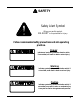
SAFETY Safety Alert Symbol BE When you see this symbol, ALERT to the potential for injury. Follow recommended safety precautions and safe operating practices. Danger indicates an imminently hazardous situation which, if not avoided, will result in death or serious injury. Warning indicates a potentially hazardous situation which, if not avoided, could result in death or serious injury. Caution indicates a potentially hazardous situation which, if not avoided, may result in minor or moderate injury.
SAFETY Failure to observe the following safety instructions could result in serious injury or death. GENERAL OPERATION: • Read, understand, and follow all instructions in the manual and on the mower before starting. • Only allow responsible adults, who are familiar with the instructions, to operate the mower. • Clear the area of objects such as rocks, toys, wire, etc., which could be picked up and thrown by the blade. • Be sure the area is clear of other people before mowing.
SAFETY SLOPE OPERATION: Slopes are a major factor related to loss-of-control and tip-over accidents, which can result in severe injury or death. All slopes require extra caution. If you cannot back up the slope or if you feel uneasy on it, do not mow it! DO Mow across the slope with your Dixon ZTR - never up or down. Remove obstacles such as rocks, tree limbs, etc. Watch for holes, ruts or bumps. Uneven terrain could overturn the mower. Tall grass can hide obstacles. Use slow speed.
SAFETY CHILDREN: Tragic accidents can occur if the operator is not alert to the presence of children. Children are attracted to lawn mowers and the mowing activity. NEVER assume children will stay where they were last seen. Be alert to avoid accidents. • Keep children out of the mowing area and under the watchful care of another responsible adult. • Be alert and turn mower off if a child enters the area. • Before and during backing, look behind and DOWN for small children. • Never carry children.
SAFETY SERVICE: • Use extra care in handling gasoline and other fuels. They are flammable and vapors are explosive. Use only an approved container. Never remove fuel cap or add fuel with the engine running. Allow engine to cool before refueling. Do not smoke while refueling. Never refuel the mower indoors. Never store the mower or fuel container inside a building where there is an open flame. If fuel is spilled on clothing, change clothing immediately.
DIXON INDUSTRIES, INC. a BLOUNT company AIRPORT INDUSTRIAL PARK PO BOX 1569 COFFEYVILLE KS 67337 0945 316 251 2000 FAX 316 251 4117 DIXON LIMITED WARRANTY POLICY - COMMERCIAL MODELS 8000 Series WARRANTY: Home Owner Application: This Dixon Warranty term is for a period of three (3) years from date of purchase. Commercial Application: Dixon mowers used for commercial application are warranted for one (1) year from the date of purchase or 750 hours whichever comes first.
SPECIFICATIONS 8000 Series (Diesel Version) CHASSIS: 11 GA - rectangular tube, 7 GA reinforcement SEAT: Designed for operator comfort with padded back and arm rests. Seat is adjustable fore and aft. Mounted on operator suspension system with damper. MOWER DECK: 2 Decks are available. Both decks are made of 10 GA fabricated welded construction with 1/4 " reinforcement plate. 3 blades combine for either a 60" or 72" cut width. Deep deck with discharge tunnel. Cut height approximately 1.
CONTROLS CONTROL LEVERS Note: For access to the seat move control levers to neutral position and swing them outward. TO GO FORWARD: From neutral position, gently push both control levers forward. To increase speed, move levers further forward. TO GO BACKWARD: From neutral position, gently pull both control levers toward you. TURNING: Turning is controlled by moving one control lever slightly forward or rearward of the other. To turn left, move left lever rearward of the right lever.
CONTROLS PARKING BRAKE: A parking brake is located to the left of the seat. Engine will kill if control levers are not in the outboard position when the parking brake is engaged. To engage brake: pull up and back. To disengage brake: push forward and down. Note: The parking brake is not intended to be used as a service brake. Note: Always set parking brake before dismounting. Release parking brake before moving mower. Note: Engage parking brake before starting engine.
CONTROLS MOWER BLADE SWITCH: To engage blades: pull up on switch. To disengage blades: push down. IGNITION SWITCH: Turn to run position to energize glow plugs. Turn to start position when glow plug light turns off, then crank engine. Release when it starts. For headlights - rotate switch one notch counter-clockwise from run. NOTE: Remove key when mower is not in use. THROTTLE CONTROL LEVER: Located on control panel to operator's right. Controls engine speed.
CONTROLS 15
OPERATION INSTRUCTIONS The safe and successful operation of the Model ZTR 8000 Series Diesel version will depend upon the operator having the correct knowledge of all controls used on the mower and making good judgements about the terrain to be mowed. NEVER allow anyone to operate the mower without complete knowledge of all controls and their functions. During initial operation, "learning to drive", set throttle at slow speed. BEFORE OPERATING MOWER: 1.
OPERATION INSTRUCTIONS TESTING OF SAFETY INTERLOCK SYSTEMS: Do not operate mower if safety switches are not operating properly. Your Zero Turning Radius Mower is equipped with control interlocks for your safety. 1. 2. 3. 4. The engine will not start if the mower blades are engaged. The engine will not start unless the steering control levers are neutral "OUT" position. The engine will stop if the mower blade clutch is engaged and the operator leaves the driver's seat.
OPERATION INSTRUCTIONS STARTING INSTRUCTIONS: 1. Operator must be seated in normal operating position. 2. Set parking brake. 3. Move control levers to outboard position. 4. Assure blade clutch is off. 5. Push throttle control lever to slow setting. 6. Insert ignition key and turn to run position. Glow plug light should light. 7. When glow plug light goes off turn ignition key to "start" position. When engine starts, release ignition key. Key will return to "run" position.
OPERATION INSTRUCTIONS MOWING INSTRUCTIONS: CAUTION Be sure that deflector is properly installed on the discharge chute. 1. Start engine and set throttle at full speed. 2. Set desired cut height. 3. Release park brake. 4. Move control levers in and operate per the control instructions on Page 12. CAUTION Check the area around the mower to assure there is no one near. 5. Set RPM at approximately 1/2 speed and engage mower blades.
OPERATION INSTRUCTIONS TO LIFT SEAT: To lift the seat, move the control levers to the neutral out position. Unhook the seat damper by rotating the clip of the retaining pin off of the clevis end and remove the retaining pin. Remove the clevis end of the seat damper from the seat hold down bracket and replace the pin and rotating pin clip to lock them in place. Release the seat latch and rotate the counterbalanced seat support frame upward and forward.
CARE AND MAINTENANCE CAUTION Before performing any maintenance, turn off engine, allow to cool & remove key. Use extreme care when working on machinery. Do not wear watch or jewelry. Do not wear loose fitting clothes, and observe all common safety practices with tools. MAINTENANCE SCHEDULE Check drive and fan belts. . . . . . . . . . . . . . . . . . . . . . . . . . . . . . . . .every 50 hours Check deck serpentine belt . . . . . . . . . . . . . . . . . . . . . . . . . . .
CARE AND MAINTENANCE ENGINE: For complete maintenance and operating information of the engine, please refer to the maintenance instructions furnished by the engine manufacturer and included in your Zero Turn Radius Mower information packet. Note: Air intake screen must be kept clean. If plugged, engine may be seriously damaged by overheating. Note: Clean radiator chaff screen when it becomes covered during operation.
CARE AND MAINTENANCE CAUTION Stop engine and remove ignition key for safety. Wear heavy, thick gloves when holding onto cutter blade, avoid the sharp edge of the blade. MOWER BLADES: Check sharpness of mower blades after every 10 hours of operation. To sharpen blades, proceed as follows. A. Remove bolt and flat washer mounting blade on shaft. Remove blade. B. Blades should be discarded when worn excessively. C. Sharpen blade with a hand file, electric grinder or blade sharpener.
CARE AND MAINTENANCE LUBRICATION: A. B. C. 24 Engine: Follow engine manufacturer's recommendation. Deck spindles: Lubricate with 3 "shots" only, every 100 hours. Mower chassis: Lubricate with 3 "shots" only, every 50 hours(see zerk locations below).
CARE AND MAINTENANCE CHECKING & REPLENISHING OIL IN HYDROSTATIC TRANSMISSION Dirt or water in oil can ruin the hydrostatic transmissions. Check the oil level in hydrostatic transmission oil reservoir after every 25 hours of usage. Clean the oil reservoir cap and the area around it prior to removal. Check the oil level. Oil should be approximately 1-3/8" below top of oil tank. Replenish as needed with SAE 20W-50 motor oil. DO NOT OVERFILL.
CARE AND MAINTENANCE PARKING BRAKE ADJUSTMENT 1. Loosen the locking screw on the top knob of the brake engaging handle. 2. Rotate it clockwise to increase and counter-clockwise to decrease brake holding power. As the brake holding power is increased the force required on the handle to engage the brake increases. 3. Set the brake for the holding power required for the intended use and the desired force required to activate it. 4. Retighten the knob locking screw. HEADLIGHT ADJUSTMENT 26 1.
CARE AND MAINTENANCE HYDROSTATIC PUMPS: Before each use, check to be sure that the cooling fins of the hydrostatic pumps are clean. Excessive accumulation of oil, dirt, or trash may cause the pumps to overheat. NEVER WASH ACROSS TOP OF RESERVOIR WITH WATER OR STEAM. Fill reservoir as required per the maintenance schedule listed in this book. HYDROSTAT DRIVE BELT REPLACEMENT PROCEDURE: To remove hydrostat pump drive belt: (The hydrostat pump drive is equipped with a spring loaded belt take-up). 1. 2. 3. 4.
CARE AND MAINTENANCE STEERING CONTROL ADJUSTMENTS A. To Adjust Neutral: 1. 2. 3. 4. 5. 6. 7. 8. 9. B. To Adjust Neutral Springs: 1. 2. 3. 4. 5. 6. 28 Lift seat. (See instructions on Page 20) Block up the unit so that the drive wheels are off the ground. Loosen ball joint jam nuts on control rod. Note: The front jam nuts are left hand threads. With steering control arms in the out/neutral position, start the engine and run at fast idle.
CARE AND MAINTENANCE STEERING CONTROL ADJUSTMENTS (continued): C. To Adjust Steering Control Levers: 1. 2. 3. 4. 5. 6. D. To Adjust "In" Position of the Steering Controls 1. E. Move the levers inboard to the operating position. Adjust the steering lever stops until the steering levers have the desired clearance. To Adjust for Straight Forward Tracking 1. 2. 3. F.
CARE AND MAINTENANCE LEVELING THE DECK 1. 2. 3. 4. 5. 6. 7. 8. 9. 10. 30 Set the tire pressure on all four tires. Front casters must be rotated in the direction of forward travel. Move the tractor to a hard level surface. Put the mower deck in the number 3 deck height position. Loosen the jam nuts on the front and rear deck hangers. Rotate the 2 outer spindles so the blades point outboard. Adjust front hangers to level deck side to side. Rotate all 3 spindles until the blades are fore and aft.
STANDARD SERVICE PARTS LIST MODEL ZTR 8026D: BLADES: BLADES: P/N 12421 (60") P/N 12339 (72") ENGINE TO MOWER DECK BELT: SERPENTINE BELT: ENGINE TO HYDRO BELT: P/N 12503 (60" and 72") P/N 9758 (60") 12033 (72") P/N 12012 HYDROSTATIC TRANSMISSION FILTER: P/N 7252 BRIGGS & STRATTON AIR AND OIL FILTER PART NUMBERS: Refer to engine manufacturers manual for recommendations regarding frequency of service required for engine oil changes and air filter maintenance.
TROUBLESHOOTING 1.
TROUBLESHOOTING 5. ENGINE OVERHEATED Air intake screen or fins clogged ---------------------clean intake screen and fins Oil level too low or too high ----------------------------------------------adjust oil level Running engine too slow ---------------------------------------------run engine faster 6.
NOTES 34
OWNER INFORMATION DIXON INDUSTRIES, INC. A BLOUNT International Inc. Co.
engine exhaust from this product contains chemicals known to the State of California WARNING: The to cause cancer, birth defects or other reproductive harm. Dixon® and ZTR® are registered trademarks of Dixon Industries, Inc. DIXON INDUSTRIES, INC. A BLOUNT International Inc. Co. PO BOX 1569 COFFEYVILLE KS 67337 0945 316 251 2000 36 8000 Series (Diesel) 8026D Part No.