ZENMUSE H3-3D Gimbal User Manual V1.02 2014.06.09 www.dji.com ©2014 DJI Innovations. All Rights Reserved.
Warning & Disclaimer H3-3D gimbal is calibrated before delivery, no adjustment or modification to the gimbal is allowed. Ensure the camera is mounted to the gimbal before powering the aircraft. H3-3D gimbal is finely calibrated according to the specified camera model and lens before the delivery. User does not need to perform extra calibration. Do not attempt to modify the gimbal or mount extra component/device (such as filter, lens hood, etc.
In The Box Gimbal×1 Built-in servos and stand-alone IMU provide yaw, roll and tilt stabilization. Integrated bottom damping plate minimizes installation time. Damping Unit×1 The upper plate of the damping unit connects the gimbal with the Phantom 2. Pre-installed vibration absorbers greatly reduce the vibrations. Gimbal Controller Unit (GCU)×1 Connect gimbal controller to flight control system using CAN-Bus. 3 Power GCU and gimbal through 3S~6S power cable.
Accessory Pack – Camera securing bracket x1 Camera mounting bracket. Accessory Pack – Spare Screws ×1 M2.5x6.3:Mounting camera to gimbal. M2.5x5:Secure gimbal to damping unit. M3x8, M3x6.5:Securing gimbal to aircraft. Accessory Pack – Gimbal Video signal Cable ×1 For the gimbal controller unit and your wireless video transmission module connection, transmitting the video signal. DJI Use CAN-Bus to connect the GCU with the flight control system.
Table of Content WARNING & DISCLAIMER ...............................................................................................2 PROFILE ..........................................................................................................................2 IN THE BOX .....................................................................................................................3 TABLE OF CONTENT ..................................................................................................
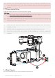
1 Installation 1.1 Gimbal Description Notes: (1) Ensure the gimbal servos are unobstructed, failure to do so may damage the servo. (2) Clear the obstacles at once if the operating gimbal is being blocked. (3) Always mount camera before powering on the gimbal. 1.1.1 Rear View 1 12 3 1 18 4 1 17 6 1 15 1. Yaw servo driver module 2. Upper plate of damping unit 3. Vibration absorbers 4. Bottom plate of damping unit 5. Tilt servo driver module 6. Roll servo driver module 7.
1.2 Install H3-3D to Phantom 2 Follow the below instructions to install the H3-3D gimbal to Phantom 2. 1. Insert the securing pins through the holes on the highlighted diagonal position shown below. Then, attach and secure the upper plate of damping unit to the Phantom 2 with four M3x5 screws. 2. Attach the damping unit bottom plate to upper plate using the four vibration absorbers. Ensure the lip of the vibration absorbers are properly inserted through the mounting holes on the bottom plate.
3. Insert washers into securing pins to lock the damping unit in place. 4. Plug the 8-pin cable from the Phantom 2 to the Phantom 2 port on the anti-interference enhancement board, then connect the H3-3D port on the anti-interference enhancement board with the 8-pin port on the gimbal via the supplied 8-pin cable. Caution: (1) Aircraft and accessories are not included with gimbal. (2) Camera must be aligned with the nose of the aircraft. (3) Gimbal is calibrated before delivery.
(6) The 8-pin port on the H3-3D gimbal should only be used for connecting to the Phantom 2. Do not connect other devices (such as a video downlink transmitter) to this port, otherwise the gimbal may be damaged. 1.3 Camera Installation Follow the below instructions to mount the GoPro camera. Caution: (1) Visit http://www.dji.com/cn/product/zenmuse-h3-3d/video, and watch installation video tutorial before you proceed to mount the GoPro camera to the H3-3D gimbal.
2 GCU Connection GCU Port Description 3S~6S G8 Connect to battery for GCU or gimbal power Connect to G8 pin port on the gimbal for signal transmission Connect to PC to upgrade firmware using Assistant Software Connect to flight control system Connect to wireless video downlink module 2.1 Connect GCU and Flight Control System Notes: (1) Skip this chapter if you purchase the Phantom 2 version of H3-3D gimbal, as it does not come with GCU.
Assistant A2 WKM NAZA-M V2 NAZA-M V 1.20 (or higher) V2.00(or higher) V2.12(or higher) V2.12(or higher) V 2.10 (or higher) V5.22(or higher) V3.12(or higher) V3.12(or higher) Software Firmware Version Step 2. Complete the connection on the flight control system (shown as the below table). For NAZA-M user, you need a PMU V2 module (accessory of NAZA-M V2) to provide with the CAN port connection.
assigns a specified channel (X3 channel for WKM, X1 for NAZA-M and H3-3D for A2) to control the tilt motion of the gimbal. To activate the tilt function, user needs to properly set up the channel in the Assistant Software and ensure the connection between the receiver and the main controller is correct. Refer to the Gimbal Assistant Software for details. 2.
Fig.2 NAZA-M V2 Connection Diagram To Battery Note: The PMU and GCU can both connect to the same battery. Leave as-is Gimbal Tilt Control Control the tilt motion via X1 channel. Properly configure the corresponding channel on the remote controller. Fig.3 NAZA-M Connection Diagram ©2014 DJI Innovations. All Rights Reserved.
2.2 Video Connection. Wireless video transmission transfers video signal from the on-board camera to the GCU via the gimbal video signal cable. Follow the figure below to complete the connection. Gimbal Video Signal Cable Wireless Video Transmission Module External power Power Air System Video Signal GND Leave as-is Video Signal(Yellow:AV) GND(Black: ) Video Signal Port 1. Solder the Video Signal/GND cables to wireless video transmission module (air system). 2.
3 Configuration 3.1 Driver and Assistant Software Installation Notes: (1) The content of this chapter does not apply to the Phantom 2 version of the gimbal. Refer to Phantom 2 Assistant Software on the DJI website instead. 1. Ensure the drivers for the flight control system are properly installed. 2. Download the Assistant Software from DJI official website. 3. Launch Assistant Software installer and follow the prompted steps to finish installation. 4. Run the Assistant Software. 3.
Fig.1 Tilt Upwards Fig.2 Tilt Downwards 3.4 Firmware & Software Upgrade 3.4.1 Firmware Upgrade Follow the below procedures to upgrade the firmware upgrade, failure to do so might damage the gimbal: 1. Ensure your computer has access to the internet. 2. Close all the other applications (anti-virus application or firewall) before upgrading the firmware. 3. Make sure the power supply is securely connected. DO NOT unplug the power supply before the upgrade completes. 4.
4 Test Fly 4.1 Check List Before Flight For safety reasons, check of the following items before each flight: (1) Gimbal is firmly installed to aircraft, and camera mounted correctly. Make sure the camera is aligned parallel with nose direction of the aircraft. (2) All cables are firmly and correctly connected. (3) Ensure gimbal video signal cable is in solid soldering condition. (4) Make sure the wireless video transmission module is connected to GCU before powering on the system.
Place the aircraft on flat surface during the test. When conducting the test while you are holding the aircraft by hands, bear in minds not to tilt the aircraft beyond 35° Do not land the aircraft with powered-on gimbal on uneven terrain (such as grass lawn or rocky roads), in which environment there may have external forces act on the gimbal otherwise the gimbal may enter hibernation due to external forces. Hibernation mode offers protection for the gimbal.
©2014 DJI Innovations. All Rights Reserved.
Specifications General Built-In Functions (1) 3-axis gimbal (2) High precision brushless servo control (3) Aluminum alloy body (4) Built-in IMU module (5) Lightweight (6) A2, WKM, NAZA-M, NAZA-M V2 ,PHANTOM 2 supported (7) GoPro3 and GoPro3+ supported (8) Zenmuse technology Peripheral Supported Camera GoPro3, GoPro3+ (black or silver version) GCU Input Power 3S~6S LiPo (12V~26V) Assistant Software System Requirement Windows XP SP3; Windows 7; Windows 8 Mechanical & Electrical Characte