
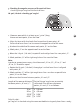
Product Manual


Horizontal checking
1. Horizontal checking - Line level
Two parallel wall surfaces at least 5m /16‘5“ apart are required for the horizontal check.
Measure the vertical distance
between point 1 and point 3.
The dierence must not be
greater than:
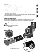
1. Place the LA90L / LA180L on a smooth surface or on a tripod as close
as possible to wall A and with the front side pointing towards the wall
2. Switch the unit on - button (1a)
3. Switch on the horizontal laser line - button (1c)
4. Switch on the vertical laser lines - button (1d)
5. Mark the position of the visible laser line cross on the wall A (point 1).
6. Turn the complete unit 180° without altering the height of the laser.
7. Mark the position of the visible laser line cross on the wall B (point 2).
8. Now move the unit directly in front of wall B.
9. Set the unit‘s height so that the laser dot‘s height matches that of point 2.
10. Without changing the height of the laser, rotate it 180° to place the beam
near the mark on the rst wall (step 3 / point 1 ).
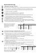
2. Horizontal checking - inclination of the laser line
Check the laser line for inclination and perfectly straight projection
1. Mark three points (1, 2 and 3) on the floor at a distance of 5 m /16’5”
from each other; the points must be in a perfectly straight line.
2. Position the laser at distance S = 5 m / 16‘5“ from the line and exactly in
front of the middle point you marked = position X
3. Switch the unit on - button (1a)
4. Switch on the horizontal laser line - button (1c)
5. Measure the height of the laser line at the points. Measurements X1 - X3
6. Reposition the instrument.
7. Position the laser at distance S = 5 m / 16‘5“ from the line and exactly in
front of the middle point you marked = position Y
8. Measure the height of the laser line at the points. Measurements Y1-Y3
Δ1 = X1 - Y1 Δ2 = X2 - Y2 Δ3 = X3 - Y3
When calculating, always take
note of the preceding prex !
I1
I2
I3
G1
G2
G3
G4
G5
(1a)
(1c)
(1d)
S Maximum permissible dierence
5 m 16‘5“ 1,0 mm 5/128“
10 m 32’10” 2,0 mm 5/64“
15 m 49’3” 3,0 mm 1/8“
20 m 65’8” 4,0 mm 5/32“
L Δ ges 1 or Δ ges 2
5 m 16‘5“ 2,0 mm 5/64“
7,5 m 24’8” 3,0 mm 1/8“
10 m 32’10” 4,0 mm 5/32“
Δ ges 1 = Δ 1 - Δ 2 < ± 2mm ± 5/64“
Δ ges 3 = Δ 3 - Δ 2 < ± 2mm ± 5/64“