Zenmuse Z15-GH3 User Manual V1.02 2013.12.26 Revision www.dji.com ©2013 DJI Innovations. All Rights Reserved.
Warning & Disclaimer No adjusting or amending is allowed to Z15. Z15 is specialized for Camera and Lens before it leaves the factory. Please mount your camera to Z15 when get it. No adjusting or amending is allowed to Z15. Do not modify or add any other component/device (such as filter, lens hood, etc.) to the camera; make sure to use the original battery; otherwise it may ends up with worse performance or even internal malfunction.
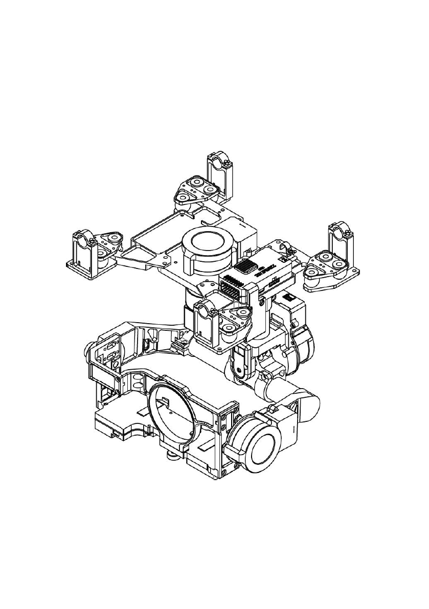
Product Profile Z15 is an excellent gimbal designed for AP. The gimbal has built-in slip ring in the mechanical structure, preventing wire rod from winding up. It also has built-in independent IMU module, special servos drive module, HDMI- AV module, etc. Excellent job can be done by Z15 in any working mode, including Orientation-locked control, Non orientation-locked control and FPV Mode (Reset).
In the Box Gimbal ×1 In the mechanical structure, the gimbal has built-in slip rings, preventing wire rod from winding up, which also enables free rotations for the 3 axes rotating rods. The gimbal has built-in Z15 gimbal special servos drive module, independent IMU module and HDMI-AV module. Gimbal Controller Unit (GCU)×1 Connect the gimbal controller to the flight control system by CAN- Bus. The GCU will control the gimbal’s pan, roll and tilt rotation.
For camera mount. Lens Retaining Ring Screw×1 For fixing the lens retaining ring to the gimbal. Screw×8 For mounting gimbal to aircraft (M2.5*8 Head-cup screw). Gimbal Video Power Cable×1 For GCU and Wireless Video Transmission Unit connecting, transmitting AV signal. Micro-USB Cable×1 For adjusting parameter and upgrading firmware via PC. DJI Use CAN-Bus to power and communicate with the flight control DJI CAN-Bus Cable×1 system Spare Package×1 Damping units, Spare Screw, and Mounting Bracket.
Contents WARNING & DISCLAIMER ...............................................................................................2 PRODUCT PROFILE ..........................................................................................................3 IN THE BOX .....................................................................................................................4 CONTENTS ......................................................................................................................
Gimbal Description Notes: Ensure nothing blocks the servo driver module rotation, to avoid motor damage. Clear obstacle at once if the rotating gimbal is blocked. Tips: Servo driver module is with two motor command input ports and one encoder private port. HDMI-AV module converts HDMI video signal to AV video signal with a cable connecting to camera HDMI port; also transforms TX signal into shutter control signal with a shutter control module.
Camera Setup Configure your camera by the following settings to meet the requirements of Z15. Please read the related content according to your camera. Panasonic GH3 SC N C3 C2 C1 MF AFC AFS /AFF M S A P iA M M ). Please set the Mode as Creative video ( MF/AFC/AFS/AFF Select: Select AFC. Select the Shutter-priority AE mode in the Menu and adjust the shutter speed to 200. Please enable the AF when using the Auto Focus function.
Mount Mount Lens Camera Retaining Ring Lens step1: Mount the lens onto the camera first, and then put the retaining ring through lens until it is fixed. Mount Camera into Gimbal Camera Mounting Screw Lens Retaining Ring Screw step2: Mount the camera into the gimbal. step3: Adjust the camera and tighten the camera mounting screw, then tighten the lens retaining ring screw. ©2013 DJI Innovations. All Rights Reserved.
Mount Gimbal to Landing Gear Following diagram shows mounting gimbal to DJI Innovations S800 EVO. You may mount the gimbal to a landing gear prepared by yourself referring to the following diagram. step4: Install the gimbal to a landing gear with mounting bracket; tighten up the screws (2.5*8 Head-cup screw×8) with appropriate screw glue. Notes: Ensure to mount the side of servo driver module1 without ports to the aircraft nose direction.
Do not unplug any cable attaching to the gimbal ports, or even change the mechanical structure. Make sure the wiring is correct, otherwise may lead to gimbal abnormal work or even out of control. ©2013 DJI Innovations. All Rights Reserved.
Camera Wiring/Shutter Control Camera Wiring Connect the camera correctly, since the gimbal works with a HDMI-AV module for converting video signal format and transforming TX signal into shutter control signal. Ensure the camera is setup first, and then carry out the following procedures to connect the camera and gimbal.
Shutter Control The Z15 enables transforming TX command into shutter control signal, please set one 2-position switch/channel for remote shutter control. Make sure the shutter control module is correctly mounted and wired. Whichever 2-position switch on your transmitter selected, wire the right channel of receiver to SHUT port.
Video Signal Transmission A wireless video transmission module is required for the video signal accessing remotely. Wireless Video Transmission Module Power Air End Gimbal Video Power Cable Connect to the power source according to the module’s voltage and current requirements. Video Signal Port Video Signal Disconnected GND Video Signal(Yellow:AV) GND(Black: ) step1: Carefully solder the corresponding Video Signal/GND cables to a wireless video transmission module (Air End).
GCU Wiring GCU Wiring WKM/ ACE ONE/ ACE Waypoint USB Port PC connection for configuration and firmware upgrades with an USB cable.
GCU Ports Indication The following table shows the GCU channels and TX channels connection. TX Channels GCU Indications JR Futaba/Hitec Channels AILE 1 ROLL For roll axis control (left/right). Velocity is zero if disconnection. ELEV 2 TILT For tilt axis control. Velocity is zero if disconnection. RUDD 4 PAN For pan axis control. Velocity is zero if disconnection. AUX2 7 MODE 2-position switch channel SHUT 2-position switch channel AUX1 For Working Mode switch.
Working Modes/HDMI/AUX2 Switch Setup Working Mode Switch Set Whichever 3-position switch selected as working mode switch, wire the right channel of receiver to MODE port. At each switch position, use end-point fine tuning, set the channel AUX2(JR) /7(Futaba/Hitec) for the three Working modes.
AUX2 Switch Set The Z15 supports to control the camera lens down or forward in Reset Mode. Please wire the right channel of receiver to AUX2 port. You may assign: Position-1 to DOWN; Position-2 to FORWARD; or reverse the assignment. 2-position switch 1 2 Tx Notes: This function can only work in FPV Mode (Reset). When this function is on, if the working mode switch from other modes to FPV Mode (Reset), the gimbal will force the camera lens to face forward or down depending on AUX2 Switch.
Assistant Software Installation and Usage step1: Make sure the driver is installed correctly, which has been installed before you use WKM,ACE ONE or ACE WAYPOINT. step2: Please download the assistant software installer from DJI Innovations website. step3: Double click the assistant software installer file and follow the steps to finish installation. step4: Run the assistant software. step5: Please upgrade the firmware or configure the parameters according to the assistant software indication if necessary.
Flight Test step1: Ensure the batteries are fully charged for transmitter, GCU and all the other devices on your aircraft. step2: Make sure all connections and wirings are in good condition. step3: Switch on the TX. step4: Make sure to adjust the Roll axis of gimbal to be level. step5: Power on the gimbal and wait for self-testing. The Roll axis will rotate first, and then the yaw and pitch axes will rotate quickly at the same time.
Appendix Matters Needing Attention For safety reasons, please pay serious attention to all of the following items: Ensure nothing blocks the servo drive module’s total range of movement, to avoid motor damage. Before powering on, spin the gimbal by hand through the complete rotational axes to ensure nothing is blocking the mechanical movement of the gimbal. Be sure to mount the side of servo drive module1 with ports facing towards the aircraft’s tail.
1-Pilot Solution 3-Position Switch 3-Position Switch 3-Position Switch 3-Position Switch 2-Position Switch 2-Position Switch 2-Position Switch 14-Channel RC Receiver (Futaba) Gimbal Control Aircraft Control 1 (AILE) 2 (ELEV) 3 (THRO) 4 (RUDD) 5 (GEAR) 6 (Collective Pitch) 7 (Control Mode Switch) Tx or This is the example connection. Prepare one 14-channel TX/RC receiver for aircraft and gimbal control.
2-Pilot Solution Rx1 2-Position Switch Gimbal Control 2-Position Switch 2-Position Switch AUX2 RC Receiver (JR) RUDD ELEV AILE 8-Channel Or 1 2 4 7 Tx1 8-Channel RC Receiver (Futaba / Hitec) 2-Position Switch 2-Position Switch 2-Position Switch Or Aircraft Control Rx2 Or AUX2 RC Receiver (JR) RUDD ELEV AILE 8-Channel THRO AUX2 S-Bus S-Bus Receiver (Futaba) PPM PPM Receiver Or Tx2 RC Receiver (Futaba / Hitec) 8-Channel 1 2 3 4 7 Or Futaba S-Bus S-Bus WKM Or ACE ONE ACE Waypoint
Port Description GCU ROLL For roll axis control TITL For tilt axis control PAN For pan axis control MODE For Working Mode switch SHUT For camera shutter control AUX1 For HDMI switch AUX2 For Gimbal orientation (down or forward) switch in FPV Mode AUX3 PPM Receiver S-Bus Receiver To wireless video transmission unit, transmitting AV signal XT60 To battery (To GIMBAL if DJI Innovations S800 used) G6 To Gimbal, transmitting motor command G8 To Gimbal, transmitting video signal Micro-USB po
Trouble Shooting NO.
Wireless video transmission supported Camera shutter control supported Wide range voltage input supported S-Bus/PPM Receiver supported Peripheral Supported Camera Panasonic GH3 Supported Lens Currently OLYMPUS M.ZUIKO DIGITAL ED 12mm f2.