Zenmuse Z15 User Manual V2.0 2013.03.27 Revision www.dji-innovations.com ©2012 DJI Innovations. All Rights Reserved.
Warning & Disclaimer No adjusting or amending is allowed to Z15. Z15 is specialized for Camera and Lens before it leaves the factory. Please mount your camera to Z15 when get it. No adjusting or amending is allowed to Z15. Do not modify or add any other component/device (such as filter, lens hood, etc.) to the camera; make sure to use the original battery; otherwise it may ends up with worse performance or even internal malfunction.
Product Profile Z15 is an excellent gimbal designed for AP. The gimbal has built-in slip ring in the mechanical structure, preventing wire rod from winding up. It also has built-in independent IMU module, special servos drive module, HDMI- AV module, etc. Excellent job can be done by Z15 in any working mode, including Orientation-locked control, Non orientation-locked control and FPV Mode (Reset).
In Box Gimbal ×1 In the mechanical structure, the gimbal has built-in slip rings, preventing wire rod from winding up, which also enables free rotations for the 3 axes rotating rods. The gimbal has built-in Z15 gimbal special servos drive module, independent IMU module and HDMI-AV module. Gimbal Controller Unit (GCU)×1 Connect the gimbal controller to the autopilot system by CAN bus. The GCU will control the gimbal’s pan, roll and tilt axes rotation.
Quick Twist Screw for Hot Shoe ×1(Z15-G) For fixing the hot shoe to camera. Quick Twist Screw for Camera ×1(Z15-G) For fixing the camera to gimbal. Screw×10(Z15-N) or Screw×8(Z15-G) For mounting gimbal to aircraft (2.5*8 Head-cup screw×8). (OnlyZ15-N needs)For fixing the lens retaining ring (M2.5*5 Screw×2). Gimbal Video Power Cable×1 For gimbal controller and Wireless Video Transmission Unit connecting, transmitting AV signal. Micro-USB Cable×1 For adjusting parameter and upgrading firmware via PC.
Contents WARNING & DISCLAIMER ...............................................................................................2 PRODUCT PROFILE ..........................................................................................................3 IN BOX ............................................................................................................................4 CONTENTS ......................................................................................................................
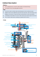
Matters Need Attention For safety reasons, please pay serious attention to all following items: Ensure nothing blocks the servo driver module rotation, to avoid motor damage. Camera’s HDMI resolution should be set to 1080i. Ensure to mount the side of servo driver module1 without ports to the aircraft nose direction. The gimbal center of gravity has been set, whose position directly determine gimbal performance. Please do not adjust the gimbal center of gravity by yourself.
Gimbal Description Notices: Ensure nothing blocks the servo driver module rotation, to avoid motor damage. Clear obstacle at once if the rotating gimbal is blocked. Tips: Servo driver module is with two motor command input ports and one encoder private port. HDMI-AV module converts HDMI video signal to AV video signal with a cable connecting to camera HDMI port; also transforms TX signal into shutter control signal with a shutter control module.
Z15-G Pan ±360° continuous rotation Mounting Bracket Motor Command Input Port (To GCU G6) Servo Driver Module 1 Damping Unit Port of 8-Pin Cable (To GCU G8) Servo Driver Module 3 HDMI-AV Port Servo Driver Module 2 Cameral Mount Position Hot Shoe Camera Mount Screw-hole Roll Shutter Control Cable ±40° (±360° mechanic continuous rotation) Gimbal LED Indicator HDMI-AV Module IMU Module Servo Driver Module Port ±360° continuous rotation Tilt ©2012 DJI Innovations. All Rights Reserved.
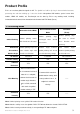
Camera Setup Configure your camera by following the settings, meeting the requirements of Z15. Please read the related content according to your product (Z15-N or Z15-G). Sony NEX-5N /7 /5R Menu Shot Mode Camera Image Size Brightness/ Color Playback Setup Shot Mode Camera Manual Exposure Drive Mode M AF/MF Select 1/60 Shutter Aperture Brightness/Color Remote Cdr. ISO MF Not use Auto White Balance Not use Auto Setup Lens Comp: Shading Lens Comp: Distortion Off HDMI Resolution F3.
Tips: In the Menu settings, the mandatory values are in red italic font while recommended values in blue. Notices: Flashing image output may occur if not follow the recommended settings. ©2012 DJI Innovations. All Rights Reserved.
Mount Mount Lens(Z15-N)/ Mount Hot Shoe(Z15-G) Please read the related content according to your product (Z15-N or Z15-G). For Z15-N, please read Mount Lens, otherwise read Mount Hot Shoe for Z15-G. Mount Lens (Z15-N) Step1 Step2 Step3 Screw L-Connector Jackscrew Camera Retaining Ring Lens Mark align align Shim Step1: Put retaining ring through lens before mounting onto camera, accurate the alignment by matching the mark.
Mount Camera into Gimbal Please read the related content according to your product (Z15-N or Z15-G). Z15-N Retaining Ring Screw Jackscrews and Other Screws Camera Mounting Screw Step4: Mount the camera into the gimbal and tighten the camera mounting screw. Step5: Adjust the L-Connector, and fix the retaining ring screw. Step6: Tighten the jackscrews and other screws. Z15-G: Quick Twist Screw for Camera Camera Mounting Screw Step4: Mount the camera into the gimbal.
Mount Gimbal to Bi-pod Following diagram shows mounting gimbal to DJI Innovations S800 bi-pod. You may mount the gimbal to a bi-pod prepared by you referring to the following diagram. Screws Mounting Bracket Parallel N raft Airc ose Camera Gimbal Lens X Y Step7: Z DJI S800 Bi-pod Install gimbal to a bi-pod with mounting bracket; tighten up screws (2.5*8 Head-cup screw×8) with appropriate screw glue.
Camera Wiring/Shutter Control Camera Wiring Connect the camera correctly, since the gimbal works with a HDMI-AV module for converting video signal format and transforming TX signal into shutter control signal. Please read the related content according to your product (Z15-N or Z15-G). Ensure camera is setup first, and then follow the procedures to connect camera and gimbal.
When disconnect the cable between HDMI-AV module and camera, dismount the camera, and unplug the HDMI-AV interface. (Z15-N) Make sure the infrared signal emission unit is aligned to the remote sensor. Shutter Control Z15 enables transforming TX command into shutter control signal, please set one 2-position switch/channel for remote shutter control. For Z15-N, set the Drive Mode as Remote Cdr. in Camera Menu, and make sure the shutter control module is correctly mounted and wired.
Video Signal Transmission A wireless video transmission module is necessary for video signal accessing remotely. Gimbal Video Power Cable Wireless Video Transmission Module Power Air End Video Signal Port Video Signal Power(Red:1A@12V) GND Video Signal(Yellow:AV) GND(Black: ) Step1: Respectively solder the Power/Video Signal/GND cables to wireless video transmission module (Air End). Step2: Plug the gimbal video power cable head into the GCU Video Signal Port.
Gimbal Controller Wiring GCU Wiring WKM/ ACE ONE/ ACE Waypoint USB Port PC connection for configuration and firmware upgrades with an USB cable.
GCU Ports Indication Following table shows the GCU channels and TX channels connection. TX Channels GCU Indications JR Futaba/Hitec Channels AILE 1 ROLL ELEV 2 TILT For tilt axis control. Velocity is zero if disconnection. RUDD 4 PAN For pan axis control. Velocity is zero if disconnection. AUX2 7 MODE For roll axis control (left/right). Velocity is zero if disconnection. For Working Mode switch. For camera shutter control.
Working Modes/HDMI/AUX2/AUX3 Switch Setup Gimbal Working Mode Switch Set Whichever 3-position switch selected as working mode switch, wire the right channel of receiver to MODE port. At each switch position, use end-point fine tuning, set the channel AUX2(JR) /7(Futaba/Hitec) for the three Working modes.
AUX2 Switch Set Z15 supports to control the camera lens down or forward in Reset Mode. Please wire the right channel of receiver to AUX2 port. You may assign: Position-1 to DOWN; Position-2 to FORWARD; or reverse the assignment. 2-position switch 1 2 Tx Notices: This function can only work in FPV Mode (Reset). When this function is on, if the working mode switch from other modes to FPV Mode (Reset), the gimbal will force the camera lens to face forward or down depending on AUX2 Switch.
Assistant Install Driver and Software STEP1: Make sure driver is installed correctly, which has been installed before you use WKM,ACE ONE or ACE WAYPOINT. STEP2: Please download assistant software ZenmuseInstaller.exe from DJI Innovations website. STEP3: Double click ZenmuseInstaller.exe file and follow the steps to finish installation. STEP4: Run DJI Zenmuse Assistant. GUI Connect GCU and PC via USB cable, power on GCU. 1 2 1 DJI · Tools: Upgrade.
Firmware Upgrade Please strictly follow the operation procedures for firmware upgrade, otherwise Z15 might not work properly: Step1: Make sure your computer is connected to the Internet. Step2: Please close all the other applications during firmware upgrade, including anti-virus software and firewall. Step3: Make sure the power supply is securely connected. DO NOT un-plug the power supply until firmware upgrade has finished.
Basic Make sure your setups according to Basic. ROLL/PAN/ TILT: Push the joystick on TX to obtain the stick direction and the gimbal rotation direction. If you use the DJI iOSD, you may obtain the gimbal attitude information (PAN/ TILT/ ROLL) on the bottom right corner of the display screen. The following diagram shows the gimbal rotation direction and the cursor slide direction on assistant.
Test Check Before Flight Notices: Gimbal is installed firmly to bi-pod, and camera mounted correctly and stably. All cables are in correct connection, without anyone in backwards. Gimbal video power cable is in good soldered condition if wireless video transmission module used. Correct TX settings. Camera shutter control module is correctly mounted. Correct camera setups. Correct connection between GCU and RC receiver. Normal connection between GCU and autopilot system.
Notices: If the gimbal is abnormal (unlike the diagram shows) after initializing, please turn to Trouble Shooting in Appendix. ©2012 DJI Innovations. All Rights Reserved.
Appendix 1-Pilot Solution 3-Position Switch 3-Position Switch 3-Position Switch 3-Position Switch 2-Position Switch 2-Position Switch 2-Position Switch 14-Channel RC Receiver (Futaba) Gimbal Control Aircraft Control 1 (AILE) 2 (ELEV) 3 (THRO) 4 (RUDD) 5 (GEAR) 6 (Collective Pitch) 7 (Control Mode Switch) Tx or · · This is example connection. Prepare one 14-channel TX/RC receiver for aircraft and gimbal control.
2-Pilot Solution Rx1 2-Position Switch Gimbal Control 2-Position Switch 2-Position Switch AUX2 RUDD ELEV AILE RC Receiver (JR) 8-Channel Or 1 2 4 7 Tx1 8-Channel RC Receiver (Futaba / Hitec) 2-Position Switch 2-Position Switch 2-Position Switch Or Aircraft Control Rx2 S-Bus S-Bus Receiver (Futaba) PPM PPM Receiver Or AUX2 RC Receiver (JR) 8-Channel RUDD ELEV AILE THRO AUX2 Or Tx2 1 2 3 4 7 RC Receiver (Futaba / Hitec) 8-Channel Or Futaba S-Bus S-Bus WKM Or ACE ONE ACE Waypoint Rx2
Port Description Gimbal Controller ROLL For roll axis control TITL For tilt axis control PAN For pan axis control MODE For Working Mode switch SHUT For camera shutter control AUX1 For HDMI switch AUX2 For Gimbal orientation (down or forward) switch in FPV Mode S-Bus Receiver AUX3 For Z15-N video recording control PPM Receiver To wireless video transmission unit, transmitting AV signal XT60 To battery (To GIMBAL if DJI Innovations S800 used) G6 To Gimbal, transmitting motor command G8
Gimbal LED Indicator Description LED Indicator Camera and gimbal connected Camera and gimbal disconnected Gimbal Label Description Camera Type _ Lens Type For example NEX5N_16 Camera Type SONY NEX-5N Lens Type E 16mm f/2.8(SEL16F28) ©2012 DJI Innovations. All Rights Reserved.
Trouble Shooting NO.
Specifications General Built-In Functions Three Working Modes Orientation-locked control Non orientation-locked control FPV mode (Reset) Built-in independent IMU module DJI gimbal special servos drive module HDMI- AV module Wireless video transmission support Camera shutter control support Z15-N video recording control support Wide range voltage input support S-Bus/PPM Receiver support SONY NEX-5N SONY NEX-7 SONY NEX-5R Panasonic GH2 SONY: E
Z15-G: 142mm ×76mm GCU BEC Output 10A@12V GCU Wireless Video Transmission Power 1A @12V GCU Weight 63g GCU Dimensions 64.2 mm ×34.1mm ×19.5mm Working Performance Load Weight (Reference Value) 336g(@Sony NEX-5N with Lens and Battery) 417g(@Sony NEX-7 with Lens and Battery) 344g(@Sony NEX-5R with Lens and Battery) 489g(@Panasonic GH2 with Lumix G14 mm/F2.5 and Battery) 534g(@Panasonic GH2 with Lumix G20 mm/F1.7 and Battery) Controlled Angle Accuracy ±0.