RB SERIES Digital Temperature Controller RB100/RB400 RB500/RB700 RB900 Communication Instruction Manual ® RKC INSTRUMENT INC.
z Modbus is a registered trademark of Schneider Electric. z Company names and product names used in this manual are the trademarks or registered trademarks of the respective companies. All Rights Reserved, Copyright 2008, RKC INSTRUMENT INC.
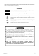
Thank you for purchasing this RKC instrument. In order to achieve maximum performance and ensure proper operation of your new instrument, carefully read all the instructions in this manual. Please place the manual in a convenient location for easy reference. SYMBOLS WARNING : This mark indicates precautions that must be taken if there is danger of electric shock, fire, etc., which could result in loss of life or injury.
CAUTION z This product is intended for use with industrial machines, test and measuring equipment. (It is not designed for use with medical equipment and nuclear energy.) z This is a Class A instrument. In a domestic environment, this instrument may cause radio interference, in which case the user may be required to take additional measures. z This instrument is protected from electric shock by reinforced insulation.
CONTENTS Page 1. OUTLINE ............................................................................... 1 2. SPECIFICATIONS ................................................................ 3 3. WIRING ................................................................................. 5 3.1 Wiring for Host Communication ....................................................................... 5 3.1.1 Communication terminal number and signal details ................................................... 5 3.1.
Page 6. MODBUS COMMUNICATION PROTOCOL ....................... 45 6.1 Message Format............................................................................................ 45 6.2 Function Code ............................................................................................... 46 6.3 Communication Mode .................................................................................... 46 6.4 Slave Responses ....................................................................................
1. OUTLINE The communication function makes it possible to monitor and set the data of the Digital Temperature Controller RB100/400/500/700/900 (hereafter called controller) from a computer. To perform communication between the computer and controller, you must create a communication program. The controller interfaces with the host computer via Modbus or RKC communication (ANSI X3.28-1976 subcategories 2.5 and A4) protocols. The communication interface used for both protocols is RS-485.
1. OUTLINE Communication Setup Tool WinUCI-B for RB series The Communication Setup Tool WinUCI-B for RB series has the following features: ・Communication data such as measured values and set values can be monitored on a personal computer screen. ・The communication data of controller can be set by the personal computer. ・Communication data can save to a personal computer. ・Communication data saved to a personal computer can be transferred to (set in) other controllers.
2. SPECIFICATIONS RKC communication Interface: Based on RS-485, EIA standard Connection method: 2-wire system, half-duplex multi-drop connection Synchronous method: Start-stop synchronous type Communication speed: 2400 bps, 4800 bps, 9600 bps, 19200 bps Data bit configuration: Start bit: Data bit: Parity bit: Stop bit: 1 7 or 8 Without, Odd or Even 1 or 2 Protocol: ANSI X3.28-1976 subcategories 2.
2.
3. WIRING WARNING ! To prevent electric shock or instrument failure, turn off the power before connecting or disconnecting the instrument and peripheral equipment. 3.1 Wiring for Host Communication The cable must be provided by the customer. 3.1.
3. WIRING 3.1.2 Wiring method Connection to the RS-485 port of the host computer (master) Controller (Slave) RS-485 Paired wire (−) (+) T/R (B) T/R (B) 15 (27) (+) *R Shielded twisted pair wire Controller (Slave) SG 13 (25) (+) (−) T/R (A) T/R (A) 14 (26) y y y (−) Host computer (Master) SG SG 13 (25) T/R (A) 14 (26) T/R (B) 15 (27) *R Maximum connections: Up to 31 controllers Screw Size: M3 × 7 (with 5.8 × 5.8 square washer) Recommended tightening torque: 0.
3. WIRING Connection to the USB of the host computer (master) Connect the USB communication converter between the host computer and the controller. Host computer (Master) Connect to USB port of a personal computer Controller (Slave) RS-485 Paired wire SG 13 (25) (−) (+) 1 SG T/R (A) 14 (26) 2 T/R (A) T/R (B) 15 (27) 3 T/R (B) 4 Unused Shielded twisted pair wire y y y y y y SG 13 (25) (+) Connect to USB connector 5 Unused COM-K (The termination resistor is built into the COM-K.
3. WIRING 3.2 Connections for Loader Communication RKC USB communication converter COM-K, loader communication cable and USB cable are required for connecting this controller to the personal computer. For the COM-K, refer to the COM-K Instruction Manual (IMR01Z01-E).
4. SETTING To establish communication parameters between host computer (master) and controller (slave), it is necessary to set the device address (Modbus: Slave address), communication speed, data bit configuration and interval time on each controller (slave) in the function block 60 (F60.) of engineering mode. 4.1 Display Sequence Power ON Display changes automatically Input type/Input range display (Display for approx.
4. SETTING 4.2 Description of Each Parameter [Function block 60 (F60.)] Symbol Name F60. Setting range Function block 60 Factory set value Description This is the first parameter symbol of function block 60. (F60.) CMPS Communication protocol 0: RKC communication 1: Modbus Use to select a protocol of communication function.
4. SETTING Interval time: The interval time for the controller should be set to provide a time for host computer to finish sending all data including stop bit and to switch the line to receive status for the host. If the interval time between the two is too short, the controller may send data before the host computer is ready to receive it. In this case, communication transmission cannot be conducted correctly.
4. SETTING Continued from the previous page. 1. Turn on the power of the controller. Press the SET key to store the new set value. The display goes to the RUN/STOP setting. Mode selection (no display) RUN/STOP setting 2. Go to the engineering mode. Press the
4. SETTING 5. Go to the function block 60 (F60.). Press the DOWN key three times at function block 00 (F00.) until function block 60 (F60.) is displayed. Function block 00 (F00.) Press the SET key to store the new set value. The display goes to the communication speed. Device address Communication speed Function block 60 (F60.) (Three times) Set the communication speed. Example: Setting the communication speed to “2 (9600 bps).” 6. Set the communication parameter.
4. SETTING Continued from the previous page. Set the data bit configuration. As an example, factory set value “0 (data bit 8, without parity bit, stop bit 1)” is set. Data bit configuration 7. Enable communication parameter After all the communications parameters are set, perform one of the following steps to make settings valid: • The power is turned on again after turning it off once. For details of setting range, refer to Data bit configuration table (P. 10). Press the SET key.
4. SETTING 4.4 Communication Requirements Processing times during data send/receive When the host computer is using either the polling or selecting procedure for communication, the following processing times are required for controller to send data: - Response wait time after controller sends BCC in polling procedure - Response wait time after controller sends ACK or NAK in selecting procedure Response send time is time when interval time is set at 0 ms.
4. SETTING RS-485 (2-wire system) send/receive timing (RKC communication) RS-485 communication is conducted through two wires, therefore, the transmission and reception of data requires precise timing.
5. RKC COMMUNICATION PROTOCOL The controller uses the polling/selecting method to establish a data link. The basic procedure is followed ANSI X3.28-1976 subcategories 2.5 and A4 basic mode data transmission control procedure (Fast selecting is the selecting method used in this controller). z The polling/selecting procedures are a centralized control method where the host computer controls the entire process.
5. RKC COMMUNICATION PROTOCOL 5.1.1 Polling procedures (1) Data link initialization Host computer sends EOT to the controllers to initiate data link before polling sequence. (2) Data sent from host computer - Polling sequence The host computer sends the polling sequence in the following formats: 1. 2. Example: 3. ENQ 0 2 M 1 ENQ Address Identifier 1. Address (2 digits) The device address specifies the controller to be polled and each controller must have its own unique device address.
5. RKC COMMUNICATION PROTOCOL 2. Identifier (2 digits) The identifier indicates the type of data (measured value, status and set value) sent to the host computer. For details, refer to 5.3 RKC Communication Identifier List (P. 27). 3. Data (6 digits) Data indicated by the identifier belonging to the controller. It is expressed in decimal ASCII code including a minus sign (-) and a decimal point. Data is not zero-suppressed. The data of “Model codes: ID” has 32 digits.
5. RKC COMMUNICATION PROTOCOL (6) ACK (Acknowledgment) An acknowledgment ACK is sent by the host computer when data received is correct. When the controller receives ACK from the host computer, the controller will send any remaining data of the next identifier without additional action from the host computer. For the identifier, refer to 5.3 RKC Communication Identifier List (P. 27). When host computer determines to terminate the data link, EOT is sent from the host computer.
5. RKC COMMUNICATION PROTOCOL 5.1.2 Polling procedure example (When the host computer requests data) Normal transmission (1) When the measured value (PV) monitor (identifier: M1) is polled Host computer send E O T 0 04H 30H 0 M Host computer send E N Q 1 30H 4DH 31H E O T 05H 04H S T X Address Identifier M 1 02H 4DH 31H 0 1 0 0 30H 31H 30H .
5. RKC COMMUNICATION PROTOCOL Error transmission Host computer send E O T 0 04H 30H 0 Host computer send E N Q 1 M 30H 4DH 31H N A K Error data 05H 15H S T X Address Identifier M 1 02H 4DH 31H 0 1 0 30H 31H 30H Identifier 0 , 0 30H 2CH 30H E T X B C C 03H To *1 Data Controller send Host computer send *1 E O T 04H S T X M 1 02H 4DH 31H Identifier 0 1 0 30H 31H 30H 0 .
5. RKC COMMUNICATION PROTOCOL 5.2 Selecting Selecting is the action where the host computer requests one of the connected controllers to receive data. An example of the selecting procedure is shown below: Host computer send E O T [Address] (1) Controller send E S T [Identifier] [Data] T [BCC] X X (2) Host computer send No response (3) (6) A C K (4) N A K (5) E O T (7) 5.2.
5. RKC COMMUNICATION PROTOCOL (3) Data sent from the host computer STX 1. 2. Identifier Data ETX BCC For the STX, ETX and BCC, refer to 5.1 Polling (P. 17). 1. Identifier (2 digits) The identifier specifies the type of data that is requested from the controller, such as set value. For details, refer to 5.3 RKC Communication Identifier List (P. 27). 2. Data Data which is indicated by an identifier of the controller is expressed in decimal ASCII code including a minus sign (-) and a decimal point.
5. RKC COMMUNICATION PROTOCOL (4) ACK (Acknowledgment) An acknowledgment ACK is sent by the controller when data received is correct. When the host computer receives ACK from the controller, the host computer will send any remaining data. If there is no more data to be sent to the controller, the host computer sends EOT to terminate the data link.
5. RKC COMMUNICATION PROTOCOL 5.2.2 Selecting procedure example (When the host computer sends the set values) Normal transmission Host computer send E O T 0 0 S T X S 1 0 1 0 04H 30H 30H 02H 53H 31H 30H 31H 30H Address Identifier 0 . E T X 0 30H 2EH 30H B C C 03H A C K Data 06H Controller send Host computer send Host computer send *1 S T X A 1 0 0 5 02H 41H 31H 30H 30H 35H Identifier 0 To *1 .
5. RKC COMMUNICATION PROTOCOL 5.3 RKC Communication Identifier List Reference to RKC communication identifier list (1) No. 1 (2) (3) (4) (5) RKC of AttriIden- No. digits bute tifier Name Measured value (PV) monitor M1 6 RO 2 Current transformer 1 (CT1) input value monitor 1 M2 6 RO 3 Current transformer 2 (CT2) input value monitor 1 M3 6 RO (6) Data range Factory set value Within input range Varies with the setting of the Decimal point position. Refer to Input range table (P.
5. RKC COMMUNICATION PROTOCOL RKC communication identifier list No. Name 1 Measured value (PV) monitor RKC No. of AttriIdenData range digits bute tifier M1 6 RO Within input range Factory set value Varies with the setting of the Decimal point position.
5. RKC COMMUNICATION PROTOCOL No. Name 11 Event 2 set value (EV2) 1, 2, 3, 4 (Event 2 set value (EV2) [high]) RKC No. of AttriIdenData range digits bute tifier A2 6 R/W Deviation action: −Input span to +Input span Input value or set value action: Same as input range Factory set value TC/RTD: 50 (50.0) V/I: 5.0 Varies with the setting of the Decimal point position.
5. RKC COMMUNICATION PROTOCOL No. Name 22 Proportional cycle time [heat-side] 1 RKC No. of AttriIdenData range digits bute tifier T0 6 R/W 0 to 100 seconds 0: Setting below 1 second is possible for Proportional cycle time [heatside] (identifier: TA). 23 Proportional band [cool-side] 3 P2 6 R/W 24 Overlap/Deadband 3 V1 6 R/W 1 to 1000 % of proportional band [heat-side] (ON/OFF control of cool-side only is not possible) TC/RTD inputs: −10 (−10.0) to +10 (+10.
5. RKC COMMUNICATION PROTOCOL No. Name 28 EEPROM mode RKC No. of AttriIdenData range digits bute tifier EB 6 R/W 0: Backup mode Factory set value 0 (Set values stored to the EEPROM when set values are changed.) 1: Buffer mode (No set values stored to the EEPROM when set values are changed.) 6 0: The content of the EEPROM does not coincide with that of the RAM. 1: The content of the EEPROM coincides with that of the RAM. R/W To release the interlock, write “0 (zero).
5. RKC COMMUNICATION PROTOCOL RKC No.
5. RKC COMMUNICATION PROTOCOL No. Name 50 Mode selection (no display) 51 Set value 2 (SV2) 52 Set value 3 (SV3) RKC No. of AttriIdenData range digits bute tifier LM 6 R/W 0 to 255 (Decimal) Set the bit data in decimal.
5. RKC COMMUNICATION PROTOCOL No. Name 63 Setting change rate limiter (up) 64 Setting change rate limiter (down) 65 F03 block selection (no display) 66 Event 1 set value (EV1’) [low] 1, 2 RKC No. of AttriIdenData range digits bute tifier HH 6 R/W 0 to Input span (Unit: °C [°F]/unit time) HL 6 R/W Varies with the setting of the Decimal point Factory set value 0 (0.0) 0 (0.0) position.
5. RKC COMMUNICATION PROTOCOL No. Name 70 Event 4 set value (EV4) 1, 2, 3, 4 (Event 4 set value (EV4) [high]) RKC No. of AttriIdenData range digits bute tifier A8 6 R/W Deviation action: −Input span to +Input span Input value or set value action: Same as input range Factory set value TC/RTD: 50 (50.0) V/I: 5.0 Varies with the setting of the Decimal point position.
5. RKC COMMUNICATION PROTOCOL No.
5. RKC COMMUNICATION PROTOCOL Write the following data (excluding No. 102 and 103) after you have switched to STOP (control stop). No. Name 89 Input type 90 Decimal point position 91 Burnout direction 92 Input scale high RKC No. of AttriIdenData range digits bute tifier XI 6 R/W TC/RTD inputs: 0 to 31 Voltage (V)/current (I) inputs: 33 to 38 Refer to Input rang table (P. 42).
5. RKC COMMUNICATION PROTOCOL No. Name 101 Transmission output scale low 1 RKC No. of AttriIdenData range digits bute tifier CW 6 R/W When MV1 is selected: −5.0 % to Transmission output scale high When PV or SV is selected: Input scale low to Transmission output scale high Factory set value Low-limit value of input span Varies with the setting of the Decimal point position. JK 6 R/W −10.0 to +10.0 % JL 6 R/W −10.0 to +10.
5. RKC COMMUNICATION PROTOCOL No. Name 112 Event 2 differential gap 1 RKC No. of AttriIdenData range digits bute tifier HB 6 R/W 0 to Input span Varies with the setting of the Decimal point position.
5. RKC COMMUNICATION PROTOCOL No. Name 123 Event 4 type 1 124 Event 4 hold action 1 125 Event 4 differential gap 1 RKC No. of AttriIdenData range digits bute tifier XD 6 R/W 0 to 23 (Refer to page 44.) WD 6 R/W 0: OFF 1: Hold action ON (When power turned on; when transferred from STOP to RUN) 2: Re-hold action ON (When power turned on; when transferred from STOP to RUN; SV changed) HD 6 R/W 0 to Input span Varies with the setting of the Decimal point position.
5. RKC COMMUNICATION PROTOCOL No. Name 134 ON/OFF action differential gap (upper) RKC No. of AttriIdenData range digits bute tifier IV 6 R/W TC/RTD inputs: 0 (0.0) to 100 (100.0) °C [°F] 135 ON/OFF action differential gap (lower) IW 136 Control output at burnout WH Varies with the setting of the Decimal point position. 6 R/W 6 Voltage (V)/Current (I) inputs: 0.0 to 10.
5. RKC COMMUNICATION PROTOCOL Input range table Do not set to any number which is not described in the input type table. This may cause malfunctioning.
5.
5. RKC COMMUNICATION PROTOCOL Relation between Event types and Event function related items 9: Set values of Event function related items valid. : Set values of Event function related items invalid.
6. MODBUS COMMUNICATION PROTOCOL The master controls communication between master and slave. A typical message consists of a request (query message) sent from the master followed by an answer (response message) from the slave. When master begins data transmission, a set of data is sent to the slave in a fixed sequence. When it is received, the slave decodes it, takes the necessary action, and returns data to the master. 6.
6. MODBUS COMMUNICATION PROTOCOL 6.2 Function Code Function code contents Function code (Hexadecimal) Function Contents 03H Read holding registers Measured value (PV), Event status and Monitor, etc. 06H Preset single register Set value (SV), Event set value, PID constants and PV bias, etc.
6. MODBUS COMMUNICATION PROTOCOL 6.4 Slave Responses (1) Normal response • In the response message of the Read Holding Registers, the slave returns the read out data and the number of data items with the same slave address and function code as the query message. • In the response message of the Preset Single Register, the slave returns the same message as the query message. • In the response message of the Diagnostics (Loopback test), the slave returns the same message as the query message.
6. MODBUS COMMUNICATION PROTOCOL 6.5 Calculating CRC-16 The Cyclic Redundancy Check (CRC) is a 2 byte (16-bit) error check code. After constructing the data message, not including start, stop, or parity bit, the master calculates a CRC code and appends this to the end of the message. The slave will calculate a CRC code from the received message, and compare it with the CRC code from the master. If they do not coincide, a communication error has occurred and the slave does not respond.
6. MODBUS COMMUNICATION PROTOCOL The flow chart of CRC-16 START FFFFH → CRC Register CRC Register ⊕ next byte of the message → CRC Register 0→n Shift CRC Register right 1 bit Carry flag is 1 No Yes CRC Register ⊕ A001H → CRC Register n+1→n No n>7 Yes No Is message complete? Yes Reverse with high-order byte and low-order byte of CRC register END The ⊕ symbol indicates an exclusive OR operation. The symbol for the number of data bits is n.
6. MODBUS COMMUNICATION PROTOCOL Example of a CRC calculation in the ‘C’ language This routine assumes that the data types ‘uint16’ and ‘uint8’ exists. Theses are unsigned 16-bit integer (usually an ‘unsigned short int’ for most compiler types) and unsigned 8-bit integer (unsigned char). ‘z_p’ is a pointer to a Modbus message, and ‘z_messaage_length’ is its length, excluding the CRC.
6. MODBUS COMMUNICATION PROTOCOL 6.6 Register Read and Write 6.6.1 Read holding registers [03H] The query message specifies the starting register address and quantity of registers to be read. The contents of the holding registers are entered in the response message as data, divided into two parts: the high-order 8-bit and the low-order 8-bit, arranged in the order of the register numbers.
6. MODBUS COMMUNICATION PROTOCOL 6.6.2 Preset single register [06H] The query message specifies data to be written into the designated holding register. The write data is arranged in the query message with high-order 8-bit first and low-order 8-bit next. Only R/W holding registers can be specified. Example: Data is written into the holding register 0006H [Set value 1 (SV1)] of slave address 1.
6. MODBUS COMMUNICATION PROTOCOL 6.6.3 Diagnostics (Loopback test) [08H] The master’s query message will be returned as the response message from the slave. This function checks the communication system between the master and slave (the controller). Example: Loopback test for slave address 1 Query message Slave address Function code 01H 08H Test code High Low 00H 00H Test code must be set to 00.
6. MODBUS COMMUNICATION PROTOCOL 6.7 Caution for Handling Communication Data • The numeric range of data used in Modbus protocol is 0000H to FFFFH. Only the set value within the setting range is effective. FFFFH represents −1. • The Modbus protocol does not recognize data with decimal points during communication. Example: When Manipulated output value (MV1) monitor [heat-side] is 5.0 %, 5.
6. MODBUS COMMUNICATION PROTOCOL 6.8 Modbus Communication Data List Reference to communication data list (1) No. (2) (3) Register address HEX DEC 0000 0 Name 1 Measured value (PV) monitor (4) Attribute RO Data range (5) Factory set value Within input range Varies with the setting of the Decimal point position. Refer to Input range table (P. 42).
6. MODBUS COMMUNICATION PROTOCOL Communication data No. Name 1 Measured value (PV) monitor Register address HEX DEC 0000 0 Attribute RO Data range Within input range Factory set value Varies with the setting of the Decimal point position.
6. MODBUS COMMUNICATION PROTOCOL No. Name 10 Heater break alarm 1 (HBA1) set value 1, 2 11 Heater break alarm 2 (HBA2) set value 1, 2 12 Control loop break alarm (LBA) time 1, 3 13 LBA deadband (LBD) 1, 3 Register address HEX DEC 0009 9 Attribute Data range Factory set value R/W 0.0 to 100.0 A 0.0 000A 10 R/W 0.0 to 100.0 A 0.0 000B 11 R/W 0 to 7200 seconds (0: Unused) 480 000C 12 R/W 0 to Input span 0 Varies with the setting of the Decimal point position.
6. MODBUS COMMUNICATION PROTOCOL No. Name 23 Proportional cycle time [cool-side] 1, 2 24 PV bias Register address HEX DEC 0016 22 0017 23 Attribute Data range R/W 0 to 100 seconds 0: Setting below 1 second is possible for Proportional cycle time [coolside] (address: 009CH). R/W TC/RTD inputs: −1999 (−199.9) to +9999 (+999.
6. MODBUS COMMUNICATION PROTOCOL No.
6. MODBUS COMMUNICATION PROTOCOL 41 Event 4 state monitor * Register address HEX DEC 0035 53 42 Error code 0036 54 43 Operation mode state monitor 0037 55 44 Actual SV selection number 0038 56 45 Auto (AUTO)/Manual (MAN) transfer 46 Interlock release 0039 57 003A 003B No.
6. MODBUS COMMUNICATION PROTOCOL No. Name 48 Mode selection (no display) Register address HEX DEC 003C 60 Attribute R/W Data range Bit data Bit 0: Auto (AUTO)/Manual (MAN) transfer a Bit 1: Set data unlock/lock transfer a Bit 2: Interlock release a Bit 3: Disable
6. MODBUS COMMUNICATION PROTOCOL No. Name 61 Setting change rate limiter (up) 62 Setting change rate limiter (down) 63 F03 block selection (no display) 64 Event 1 set value (EV1’) [low] 1, 2 Register address HEX DEC 0049 73 Attribute Data range Factory set value R/W 0 to Input span (Unit:°C [°F]/unit time) 0 (0.0) 0 (0.0) 004A 74 R/W Varies with the setting of the Decimal point position.
6. MODBUS COMMUNICATION PROTOCOL No. Name 68 Event 4 set value (EV4) 1, 2, 3, 4 (Event 4 set value (EV4) [high]) Register address HEX DEC 0050 80 Attribute R/W Data range Deviation action: −Input span to +Input span Input value or set value action: Same as input range Factory set value TC/RTD: 50 (50.0) V/I: 5.0 Varies with the setting of the Decimal point position.
6. MODBUS COMMUNICATION PROTOCOL No. Name 74 F06 block selection (no display) 75 F07 block selection (no display) 1 76 Minimum ON/OFF time of proportioning cycle [heat-side] 2 77 Output limiter high [Heat-side output limiter (high)] 78 Output limiter low [Cool-side output limiter (high)] Register address HEX DEC 0056 86 Attribute R/W 0057 87 R/W 0058 88 R/W 0059 89 R/W 005A 90 R/W 0: Display 1: No display 0: Display 1: No display 0 to 1000 ms PID control: Output limiter low to 105.
6. MODBUS COMMUNICATION PROTOCOL Write the following data (excluding No. 102 and 103) after you have switched to STOP (control stop). 85 Input type Register address HEX DEC 0061 97 86 Decimal point position 0062 98 R/W 87 Burnout direction 0063 99 R/W 88 Input scale high 0064 100 R/W No. Name Attribute R/W Data range TC/RTD inputs: 0 to 31 Voltage (V)/current (I) inputs: 33 to 38 Refer to Input rang table (P. 42).
6. MODBUS COMMUNICATION PROTOCOL No. Name 96 Transmission output scale high 1 Register address HEX DEC 006C 108 Attribute R/W Data range When MV1 is selected: Transmission output scale low to +105.0 % When PV or SV is selected: Transmission output scale low to Input scale high Factory set value High-limit value of input span Varies with the setting of the Decimal point position. 97 Transmission output scale low 1 006D 109 R/W When MV1 is selected: −5.
6. MODBUS COMMUNICATION PROTOCOL 107 Event 2 type 1 Register address HEX DEC 0077 119 108 Event 2 hold action 1 0078 120 R/W 109 Event 2 differential gap 1 0079 121 R/W No. Name Attribute R/W Data range 0 to 23 (Refer to page 44.) 0: OFF 1: Hold action ON (When power turned on; when transferred from STOP to RUN) 2: Re-hold action ON (When power turned on; when transferred from STOP to RUN; SV changed) 0 to Input span Varies with the setting of the Decimal point position.
6. MODBUS COMMUNICATION PROTOCOL No. Name 117 Event 3 output action at input burnout 1 Register address HEX DEC 0081 129 Attribute R/W 118 Energized/De-energized of Event 3 output 1 119 Event 3 timer 1 0082 130 R/W 0083 131 R/W 120 Event 3 interlock 1 0084 132 R/W 121 Event 4 type 2 0085 133 R/W 122 Event 4 hold action 2 0086 134 R/W 123 Event 4 differential gap 2 0087 135 R/W Data range 0: Event output is not forcibly turned ON when the burnout function is activated.
6. MODBUS COMMUNICATION PROTOCOL No. Name 128 CT ratio 1 (Number of turns) Register address HEX DEC 008C 140 Attribute Data range R/W 1 to 1000 129 Number of HBA delay times 1 130 Direct/Reverse action 2 008D 141 R/W 0 to 255 times 008E 142 R/W 131 Cool action 3 008F 143 R/W 132 ON/OFF action differential gap (upper) 0090 144 R/W 0: Direct action 1: Reverse action 0: Air cooling 1: Water cooling 2: Cooling gain linear TC/RTD inputs: 0 (0.0) to 100 (100.
6. MODBUS COMMUNICATION PROTOCOL No. Name 142 STOP display selection 143 Time setting of proportional cycle time [heat-side] 1, 3 144 Time setting of proportional cycle time [cool-side] 2, 4, 5 Register address HEX DEC 009A 154 Attribute R/W 009B 155 R/W 009C 156 R/W Data range 0: STOP on PV display + STOP lamp (green) lights 1: STOP on SV display + STOP lamp (green) lights 2: STOP lamp (green) lights 0: 0.1 seconds (fixed) 1: 0.25 seconds (fixed) 2: 0.
7. TROUBLESHOOTING ! WARNING z To prevent electric shock or instrument failure, always turn off the system power before replacing the instrument. z To prevent electric shock or instrument failure, always turn off the power before mounting or removing the instrument. z To prevent electric shock or instrument failure, do not turn on the power until all wiring is completed. Make sure that the wiring is correct before applying power to the instrument.
7. TROUBLESHOOTING Continued from the previous page. Problem EOT return Possible cause The specified identifier is invalid NAK return Error in the data format Error occurs on the line (parity bit error, framing error, etc.) BCC error The data exceeds the setting range The specified identifier is invalid Solution Confirm the identifier is correct or that with the correct function is specified.
8. APPENDIX 8.1 ASCII 7-Bit Code Table This table is only for use with RKC communication.
8. APPENDIX 8.2 Deviation Action, Input Value Action and Set Value Action The table below indicates whether each event function is classified as a deviation action, input value action, or set value action.
The first edition: OCT. 2008 [IMQ00] The third edition: DEC.
R RKC INSTRUMENT INC. HEADQUARTERS: 16-6, KUGAHARA 5-CHOME, OHTA-KU TOKYO 146-8515 JAPAN PHONE: 03-3751-9799 (+81 3 3751 9799) FAX: 03-3751-8585 (+81 3 3751 8585) E-mail: info@rkcinst.co.jp Website: http://www.rkcinst.com/ IMR02C16-E3 DEC.