Owner’s Manual Series 6050 and 6100 Vehicular Swing Gate Operator CO NF AN OR SI/ MS UL TO -32 CA CE 5 N/C RT SA IFIED C2 2.2 TO HI NO CU . 24 LA 7 R VE CL AS S MO DE SE RIA VO GA TE L 533 OP ER HP AT 82 OR L WA RN IN G LT S AM PS MA X GA TE LO AD Do orK ing , Inc ., PH 60 Ing AS E Hz lew oo d, CA MOV SE IN RI G GA OU Op S IN TE era and te JU CAN fre gate RY CA e of onl Do OR US peo y wh ple en or not allo DE E and gat ope AT rat w chi obs e are e gat ldr H tru a is Do ctio in e.
6050 / 6100 SPECIFICATIONS UL325 Class of Operation Type of Gate Horsepower Voltage / Phase Current Max Gate Weight Max Gate Length Cycles Per Hour Speed Entrapment Protection Model 6050 Class I Only ; Model 6100 Class I, II, III, IV Vehicular Swing Gates Only 1/2 HP 115 VAC Single-Phase Model 6050 1/2 HP – 4.3 Amps @ 120V ; Model 6100 1/2 HP – 5.4 Amps @ 120V Model 6050 - 400 Lbs. ; Model 6100 - 500 Lbs. Model 6050 - 10 Ft. ; Model 6100 - 14 Ft.
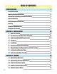
TABLE OF CONTENTS SPECIFICATIONS Gate Construction 4 Important Safety Instructions 4 Instructions regarding intended installation: 4 Important Notices 5 UL325 Entrapment Protection 6 Glossary 7 Swing Gate Requirements 8 Swing Gate Protection 9 SECTION 1 - INSTALLATION 10 1.1 Operator Position 10 1.2 Post Mount or Pad Mount Base Assembly 10 1.3 Underground Conduit Requirements 11-12 1.4 Pad Mount 13 1.5 Post Mount 13 1.6 Arm and Gate Bracket Installation 14 1.
2.6 Control Wiring 19 2.7 Loop Detector Wiring 20 2.8 Primary / Secondary (Dual) Gate Connection 21 SECTION 3 - ADJUSTMENTS 3.1 4502 Circuit Board Adjustments 3.2 DIP-Switch Settings 22 22 23-24 3.3 Automatic Limit Adjustment 25 3.4 Entrapment Sensing Adjustment (Adjustable Clutch) 25 3.5 Secondary Entrapment Protection System 25 SECTION 4 - OPERATING INSTRUCTIONS 4.1 Power and Reset Switches 4.2 Shutdown Conditions 26 26 27-28 Soft Shutdown Hard Shutdown 4.
Gate Construction Vehicular gates should be constructed and installed in accordance with ASTM F2200; Standard Specification for Automated Vehicular Gate Construction. For a copy of this standard, contact ASTM directly at 610-832-9585; service@astm.org; or www.astm.org. Important Safety Instructions WARNING - To reduce the risk of injury or death: 1. READ AND FOLLOW ALL INSTRUCTIONS. 2. Never let children operate or play with gate controls. Keep the remote control away from children. 3.
• For gate operators utilizing contact sensors: 1. One or more contact sensors shall be located where the risk of entrapment or obstruction exist, such as at the leading edge, trailing edge, and post mounted both inside and outside of a vehicular horizontal slide gate. 2. One or more contact sensors shall be located at the bottom edge of a vehicular vertical lift gate. 3. One or more contact sensors shall be located at the pinch point of a vehicular vertical pivot gate. 4.
UL325 Entrapment Protection Class I Class II A vehicular gate operator (or system) intended for use in a home of one-to four single family dwelling, or a garage or parking area associated therewith. A vehicular gate operator (or system) intended for use in a commercial location or building such as a multi-family housing unit (five or more single family units) hotel, garages, retail store or other building servicing the general public.
Glossary GATE - A moving barrier such as a swinging, sliding, raising, lowering, or the like, barrier, that is a stand-alone passage barrier or is that portion of a wall or fence system that controls entrance and/or egress by persons or vehicles and completes the perimeter of a defined area. RESIDENTIAL VEHICULAR GATE OPERATOR – CLASS I - A vehicular gate operator (or system) intended for use in a home of one-to four single family dwelling, or garage or parking area associated therewith.
Swing Gate Requirements The operator is intended for installation only on gates used for vehicles. Pedestrians must be supplied with a separate access opening. The pedestrian access opening shall be designed to promote pedestrian usage. Locate the gate such that persons will not come in contact with the vehicular gate during the entire path of travel of the vehicular gate. (ref. UL325 56.8.4.
Swing Gate Protection C Non-contact Sensor Minimizes the potential of the gate closing on vehicular or other traffic that loops cannot sense. Reverse Loop Minimizes the potential of the gate closing when a vehicle is present. Number and placement of loops is dependent on the application. D C D Shadow Loop Provides a hold open command to the operator(s) only if the gate(s) are at the full open position. D Warning Signs Permanently mounted and easily visible from either side of the gate.
SECTION 1 - INSTALLATION Prior to beginning the installation of the swing gate operator, we suggest that you become familiar with the instructions, illustrations, and wiring guide-lines in this manual. This will help insure that your installation is performed in an efficient and professional manner. The proper installation of the vehicular swing gate operator is an extremely important and integral part of the overall access control system.
1.2 Post Mount or Pad Mount Base Assembly (2) 1” bolts through the main gear bracket mounting holes. (2) 1 1/2” bolts through the main gear bracket mounting holes. Post Support Base r ato Screw the posts to the support plate and mount into concrete BEFORE attaching the operator. om ott of er Op B ort pp ate u S Pl Hardware for Post Mount: (2) 1 1/2 inch bolts. For support plate. (2) 1 inch bolts. For support plate. (3) Non-slip nuts. For existing threaded studs on bottom of operator.
1.3 Underground Conduit Requirements Primary Operator Position Secondary Operator Position Primary/Secondary Interconnection Cable (Dual Operator Application Only) Low Voltage Control and/or P.A.M.S. Wires Low Voltage Loop Lead-In Wires High Voltage Power Sweeps 3/4 Inch Minimum Concrete Pad Never run high voltage and low voltage wires in the same conduit. 1.
Mount the post base into the concrete before installing the operator. Closed Gate 1.5 Post Mount Note: 2” thick gate Illustrated. These measurements will work for standard or convenience open models from 1.1 layout on page 10 ONLY. 90° Open Gate The post mount installation will allow the operator to be mounted low enough to attach the gate bracket to the lower gate rail if desired. Concrete Position 6” 25.25” Post Base 29” Operator MUST be level. 18.
1.7 Manually Adjust the Open and Closed Gate Positions DO NOT power up the operator to set the open and closed gate positions. The first time the operator is powered up and cycled, it will automatically set the open and close limits. To do this, the arms MUST already be in the correct configuration. Closed Arms Position Open Arms Position Closed Gate 90° 90° Open Gate Open Gate Arms must be on the imaginary straight line. .5” 37 Approximate pivot point distances.
1.9 Gates Opening Wider Than 90° The installation of an operator opening gates wider that 90° is the same for 1.3 through 1.8 except the operator and concrete pad will be in a different position. Individual requirements can be calculated following this 105° demonstrated sample. n Co ng cti ne Arm Arm Assembly ” 62.25” minus (crank arm) 22.25” = 40” 40 3 Connecting arm’s pivot point measurement bly sem Closed Gate As .5” nk Cra ” 44.5” divided by 2 = 22.25” ” .
SECTION 2 - WIRING Before attempting to connect any wiring to the operator, be sure that the circuit breaker in the electrical panel is in the OFF position. Permanent wiring must be installed to the operator as required by local electrical codes. It is recommended that a licensed electrical contractor perform this work.
2.3 Main Terminal Description • When gate is closed, input will open gate. • When gate is open and auto close timer SW 1, switch 4 is turned on, input will re-set and hold timer. • When gate is open and auto close timer SW 1, switch 4 is turned off, input will close gate. • When gate is closing, input will reverse gate.
N 2 3 4 5 6 7 8 NC 17 2.4 Auxiliary Terminal Description NO 18 Tracker LEDs 19 20 4502 1 2 3 4 5 6 7 8 1. ALARM OUTPUT Provides power to activate the entrapment alarm. 2. ALARM RESET INPUT Input to reset the operator after an entrapment alarm. 3. COMMON Common for alarm output and alarm reset input. 4. TRACKER DATA Supplies gate operator data to Tracker expansion board (P/N 2351-010). Refer to the Tracker Installation and Wiring Manual for detailed information. 5.
2.6 Control Wiring B • Diagram at right is for illustration purposes. The actual placement of the secondary protection devices is dependent on the specific installation requirements. • Secondary entrapment protection devices must be installed with this gate operator. This protection may be provided by non-contact or contact sensors, or a combination of both. • Secondary device wiring shows inputs to the circuit board only. Photo-cells must be supplied with power.
2.7 Loop Detector Wiring • If other detectors are used, use a separate power supply to power these detectors. Loops and loop detectors MUST be installed with this gate operator to help prevent the gate from accidentally closing on vehicular traffic. • Loop layout shown is for a typical swing gate application with two-way traffic, or one-way exit only traffic. • Loop detector wiring is shown for DoorKing plug-in loop detectors only.
2.8 Primary / Secondary (Dual) Gate Connection Connect the Primary / Secondary interconnection wiring as shown. Wire colors are based on DoorKing interconnection cable (P/N 2600-75x). Power is supplied to the secondary operator by the interconnection cable.
SECTION 3 - ADJUSTMENTS The switch settings and adjustments in this chapter should be made after your installation and wiring to the operator(s) is complete. Whenever any of the programming switches on the circuit board are changed, power must be shut-off, and then turned back on for the new setting to take effect. 3.1 4502 Circuit Board Adjustments EXIT Power LED indicates that low voltage power is applied to the circuit board.
3.2 DIP-Switch SW 1 Settings The two DIP-switches located on the circuit board are used to program the operator to operate in various modes and to turn on or off various operating features. Whenever a switch setting is changed, power to the operator must be turned OFF and then turned back on for the new setting to take affect. Check and review ALL switch settings prior to applying power to the operator.
3.3 DIP-Switch SW 2 Settings SW 2 (Bottom 8 Switches) Switch Function OFF 1 Primary Operator Opening Direction Opening direction of arm using OFF setting. Gate opens counter-clockwise. ON Opening direction of arm using ON setting. Gate opens clockwise. Secondary Operator Opening Direction OFF Opening direction of arm using OFF setting. Gate opens counter-clockwise. ON Opening direction of arm using ON setting. Gate opens clockwise.
3.4 Automatic Limit Adjustment The FIRST time the operator is cycled, it will automatically set the open and close limits. The arms MUST be in the correct closed configuration (See 1.7 on page 14). DO NOT cycle the operator until the arms are in the correct configuration. The gate open and close positions are determined by the physical stop “flange” on the elbow assembly (See 1.6 on page 13). Activate an open device (or momentarily jump across terminals 11 and 20).
SECTION 4 - OPERATING INSTRUCTIONS IMPORTANT SAFETY INSTRUCTIONS WARNING - To reduce the risk of injury or death: 1. READ AND FOLLOW ALL INSTRUCTIONS. 2. Never let children operate or play with gate controls. Keep the remote control away from children. 3. Always keep people and objects away from gate. NO ONE SHOULD CROSS THE PATH OF THE MOVING GATE. 4. Test the operator monthly. The gate MUST reverse on contact with a rigid object or stop or reverse when an object activates the non-contact sensors.
4.2 Shutdown Conditions Under various entrapment conditions the operator will assume either a soft or hard (alarm) shutdown. To determine what type of reset action is required, you will need to understand how the different entrapment conditions affect the gate operator. Soft Shutdown This occurs in various situations where the inherent or secondary entrapment protection devices have been activated.
Resetting a Hard Shutdown When the operator is in a hard shutdown condition (audio alarm activated or audio alarm “chirps” every 5 seconds), the only way to reset the gate operator and return it to normal operation is to activate the alarm reset input (auxiliary terminals 2 and 3). An alarm-reset switch can be mounted external of the gate operator provided that it is installed in the line of sight of the gate and gate operator. • Before resetting a hard shutdown, determine why the shutdown occurred.
Fail-Safe Manual Operation The FAIL-SAFE manual operation system is the most reliable and safest method for placing an automated gate in manual operation and is the preferred method of emergency gate operation under worse case conditions by many Fire Chiefs and Building Inspectors and is typically used in CLASS I and CLASS II applications. This system requires no keys, cranks or tools for manual gate operation and is completely automatic.
SECTION 5 - OPTIONAL CONVENIENCE OPEN ADJUSTMENTS The optional convenience open system installed in your vehicular gate operator is designed as a convenience enhancement only. It is not designed or intended to provide continuous gate operation during a power outage. Its sole purpose is to provide a method to open the vehicular gate to allow unimpeded traffic flow when the gate and access control system is without power.
5.2 DC System Description Timer needs to Do Not Adjust be adjusted. Do Not Adjust Charging LED 12 V 3 Amp/Hr Red/White – + Batteries Gate will automatically or manually OPEN and stay open during an AC power failure. DIP-Switch 3 setting will determine how operator will return to normal operation once AC power has been restored.
SECTION 6 - MAINTENANCE AND TROUBLESHOOTING Inspection and service of this gate operator by a qualified technician should be performed anytime a malfunction is observed or suspected. High cycle usage may require more frequent service checks. 6.1 Maintenance When servicing the gate operator, always check any secondary (external) reversing devices (loops, photo eyes, etc.) for proper operation.
6.2 Troubleshooting Have a good VOM meter to check voltages and continuity. A Meg-Ohm meter capable of checking up to 500 meg-ohms of resistance is necessary to properly check the integrity of the ground loops. When a malfunction occurs, isolate the problem to one of three areas: 1) the operator, 2) the loop system, 3) the keying devices. Use caution when checking high voltage areas: terminals 1 through 6, the motor capacitor and the motor. 1. Check the input indicator LEDs.
Symptom Possible Solution(s) Gate opens a short distance, then stops and reverses. • • • • Check that the clutch is adjusted properly and is not slipping. Disconnect the gate from the gate operator and check that the gate swings freely without any binding. Check that SW-1, switch 7 is set correctly. Check the PULSE LED on the circuit board. PULSE 1 should blink as the primary (or single) operator is running. PULSE 2 should blink as the secondary operator is running.
6.3 Accessory Items The following accessory items are available for the model 6050 and 6100 swing gate operators. Contact Sensors - For use as a secondary entrapment protection device. Miller Edge, Inc., MGO20, MGR20, MGS20 Photo Cell - Non-contact (photo-cells) sensors for use as a secondary entrapment protection device. MMTC, Inc. Model IR55 P/N 8080-010 MMTC, Inc.
Model 6050 / 6100 6050 1/2 HP - 4.3 amp OR 6100 1/2 HP - 5.
Model 6100 / Convenience Open 50uf Capacitor Magnetic Limit Sensor Blue DC Motor 12 V 3 Amp/Hr 1/2 HP Red Red/White – + Batteries Red Red Blue White Ground Board Ground Brown 12 V 3 Amp/Hr – + Red 1 2 3 4 5 Blue Red White Purple Green Black/White Red/White Ground 6 7 8 9 Purple Yellow Brown 10 11 12 Green 1 2 3 4 5 6 7 8 White NO ON Orange NC 1 2 3 4 5 6 7 8 2340 ON 13 14 15 16 17 18 19 POWER 20 Red 1 2 3 4 5 6 7 8 4502 Red Yellow White White Convenience Outlets
Model 6050 / 6100 Secondary Operator 6050 1/2 HP - 4.3 amp OR 6100 1/2 HP - 5.4 amp 8. Gray Orange Orange 7. Orange Brown Brown Yellow Yellow 6. Brown 5. Yellow 4. Purple White White Blue Red Blue Ground Red 3. White 2. Blue 1.
Model 6100 Secondary Operator / Convenience Open Green 1/2 HP 8. Gray Orange Orange White Brown Yellow 7. Orange Brown Yellow Purple White White Blue Red Blue Ground White Red 6. Brown 5. Yellow 4. Purple 3. White 2. Blue 1.
Owner’s Manual Series 6050 and 6100 Vehicular Swing Gate Operator DoorKing, Inc. 120 Glasgow Avenue Inglewood, California 90301 U.S.A. Phone: 310-645-0023 Fax: 310-641-1586 6050-065-L-11-08 www.doorking.