Owner’s Manual Model 9310 Vehicular Slide Gate Operator DoorKing, Inc. 120 Glasgow Avenue Inglewood, California 90301 U.S.A. Phone: 310-645-0023 Fax: 310-641-1586 www.doorking.com P/N 9310-065 Rev D 5/05 Copyright 2003 DoorKing, Inc. All rights reserved.
Use this manual with the following models only. All 9310 models with circuit board 4403-010. IMPORTANT! The 4403 circuit board used in the model 9310 IS NOT interchangeable with the 4402 circuit board used in the earlier model 9300 operators.
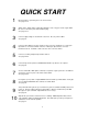
QUICK START 1 Mount operator to pad using 3/8 or 1/2 sleeve anchors. See page 14-15. 2 Attach chain. Adjust chain to allow approximately 1-inch of sag per 10-feet of gate width. Be sure to remove the pin from the breather plug. See page 16-17. 3 Connect supply voltage as described in section 2.2. Be sure power is OFF! See page 22. 4 Connect control wiring as shown. Radio receiver connects to terminals 1-2-3. Full open input devices connect to terminals 4 and 13.
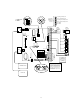
1 Open Cycle Photocell TIMER ON 1 1 DIRECTION 2 TIMER 2 Close Cycle Photocell Secondary Entrapment Protection Devices 3 Open Cycle Contact Sensor 2 4 Close Cycle Contact Sensor 3 5 Common 6 Common 12345678 9406 EXIT LOOP 4-Wire Receiver 3-Wire Receiver 1 LIMIT SWITCH CONNECTOR 24V Com Relay Radio Pwr 3 1 2 3 ON 4 1234 LIMIT LIMIT PARTIAL 24V Com -Relay Relay Radio Pwr + 1 2 5 REVERSING DEVICE CONNECTOR POWER TIME DELAY 6 7 8 9 10 REV SENS OPEN REV SENS CLOSE 11 12 13 RELA
TABLE OF CONTENTS Important Notices......................................................................................................................................................8 Important Safety Instructions ....................................................................................................................................9 Restrictions and Warnings........................................................................................................................................
Section 4 – Operating Instructions 4.1 4.2 Power and Reset Switches ......................................................................................................................39 Shutdown Conditions ...............................................................................................................................40 Soft Shutdown ..........................................................................................................................................
IMPORTANT NOTICES Vehicular gate systems provide convenience to their users and limit vehicular traffic onto your property. These systems can produce high levels of force; therefore it is important that you are aware of possible hazards associated with your gate operating system. These hazards may include pinch points, entrapment, absence of controlled pedestrian access or traffic backup. Be sure that the installer has instructed you on the proper operation of the gate and gate operator system.
IMPORTANT SAFETY INSTRUCTIONS WARNING - To reduce the risk of injury or death: 1. READ AND FOLLOW ALL INSTRUCTIONS. 2. Never let children operate or play with gate controls. Keep the remote control away from children. 3. Always keep people and objects away from gate. NO ONE SHOULD CROSS THE PATH OF THE MOVING GATE. 4. Test the operator monthly. The gate MUST reverse on contact with a rigid object or stop or reverse when an object activates the non-contact sensors.
RESTRICTIONS AND WARNINGS Install The Gate Operator Only If: The operator is appropriate for the usage Class of the application and the gate is within the weight and length limitations specified for the operator. • All openings of a horizontal slide gate are guarded or screened from the bottom of the gate to a minimum of 4 feet (1.2 m) above the ground to prevent a 2 ¼ inch (57.
ENTRAPMENT PREVENTION This vehicular gate operator is equipped with an inherent (Type A) entrapment sensing system. This system will sense an obstruction in both the opening and closing gate cycles, and will cause the gate to reverse direction should an obstruction be encountered. If the system detects a second obstruction before reaching the full open or close limit after the initial reversal, an alarm will activate and the operator will require a reset before resuming normal operation.
GLOSSARY GATE – A moving barrier such as a swinging, sliding, raising, lowering, or the like, barrier, that is a stand-alone passage barrier or is that portion of a wall or fence system that controls entrance and/or egress by persons or vehicles and completes the perimeter of a defined area. RESIDENTIAL VEHICULAR GATE OPERATOR-CLASS I - A vehicular gate operator (or system) intended for use in a home of one-to four single family dwelling, or garage or parking area associated therewith.
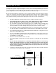
SECTION 1 - INSTALLATION Prior to beginning the installation of the slide gate operator, we suggest that you become familiar with the instructions, illustrations, and wiring guide-lines in this manual. This will help insure that your installation is performed in an efficient and professional manner. The proper installation of the vehicular slide gate operator is an extremely important and integral part of the overall access control system.
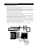
1.2 Concrete Pad The model 9310 vehicular gate operator is designed to be mounted on a concrete pad. 1. Construct a form for the mounting pad according to the specifications shown below. Note that the pad for the 1 HP operator extends an additional 6 inches to the right to accommodate the larger cover. Be sure to level the top edge of the form and that the top of the form is a minimum of four (4) inches above ground level.
1.3 Operator Installation • Position the operator on the pad so that there is a minimum clearance of one (1) inch between the back of the operator housing and the gate. • IMPORTANT!! Be sure that the operator is parallel to the gate! Installing the operator in any other manner will cause excessive chain noise, chain wear and stretching, and premature idler failure. • Mark the mounting holes on the mounting pad.
1.4 Chain Installation 1. Secure the chain brackets to each end of the gate so that the brackets are level with the top chain cutouts in the operator housing. Brackets should be attached to the inside of the frame so that the chain bolts, when attached, do not protrude beyond the frame of the gate. 2. Remove the breather plug pin from the gear-box and discard it (page 17). 3. Route the chain through the gate operator: under the chain guide idlers and over the drive sprocket. 4.
1.
1.
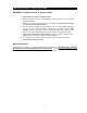
1.7 Warning Sign Installation This DoorKing slide gate operator is shipped with two warning signs. The purpose of the warning signs is to alert uninformed persons, and to remind persons familiar with the system, that a potential hazard may exist so that appropriate action can be taken to avoid the hazard or to reduce exposure to the hazard. 1. Permanently install the supplied warning signs in locations so that the signs are visible by persons on both sides of the gate. 2.
SECTION 2 – WIRING Before attempting to connect any wiring to the operator, be sure that the circuit breaker in the electrical panel is in the OFF position. A separate power disconnect must be installed at the operator location. Permanent wiring must be installed to the operator as required by local electrical codes. It is recommended that such work be performed by a licensed electrical contractor. 2.
2.2 High Voltage Connections Use Table 1 to determine high voltage wire size requirements. The distance shown in the chart is measured in feet from the operator to the power source. If power wiring is greater than the maximum distance shown, it is recommended that a service feeder be installed. A separate power disconnect must be installed at the operator. The wire table is based on stranded copper wire.
2.3 Control Wiring Controls must be far enough from the gate so that the user is prevented from coming in contact with the gate while operating the controls. Outdoor or easily accessible controls should have a security feature to prevent unauthorized use. • Connect optional control devices to the operator terminal strip as shown below. Check your connections carefully! The 4403 circuit board has different wiring terminals than the 4402 circuit board found in the older model 9300 operator.
2.4 Secondary Entrapment Non-Contact Sensors • Before connecting non-contact or contact sensors, refer to page 32 for operational description of these sensors. • Disconnect power to the gate operator before installing the non-contact sensors. • See diagram below for suggested placement of sensors. (Diagram is for illustration purposes only. Actual placement of the sensors is dependent on the installation requirements).
2.5 Contact Sensors • Before connecting non-contact or contact sensors, refer to page 32 for operational description of these sensors. • Disconnect power to the gate operator before installing the contact sensors. • Connect the contact sensors as shown below to the auxiliary terminal strip located on the 4403 control board. • Contact sensors may be located at the leading edge, trailing edge, and post mounted both inside and outside of the vehicular sliding gate.
2.6 Loop Detectors Loops and loop detectors must be installed with this gate operator to prevent the gate from accidentally closing on vehicles that may be in the path of the gate. • Loop detector wiring is shown for DoorKing model 9406 Plug-In loop detector only. If other loop detectors are used, refer to the installation instructions supplied with those detectors for wiring requirements. • If other loop detectors are used, all inputs to the terminal strip are NORMALLY OPEN.
2.7 Gate Tracker This gate operator is equipped with outputs from the circuit board that will report operator status to a companion DoorKing Access Control System (Model 1833, 1835, 1837 or 1838) when equipped with an optional Tracker expansion board. This report includes items such as gate operator cycle count, any shorted inputs, loop detector problems, any attempts to force the gate open, if the gate has struck anything during the open or close cycle, power interruptions, etc.
2.8 Alarm Reset Switch The gate operator is equipped with a built-in reset switch that will silence the entrapment alarm and return the operator to normal operation after a hard shutdown occurs. An auxiliary reset button may be added provided that the following condition is met. • The alarm-reset button must be located in the line of sight of the gate. Connect the normally open alarm-reset switch to auxiliary terminals 13 and 15.
2.10 Master / Slave Wiring The interface wiring between the two operators requires four (4) 18 AWG wires for control. Each operator must be connected to it's own power source as described in section 2.2. Be sure that both operators are wired to the same phase in the breaker panel. Check at the breaker panel by measuring voltage from HOT to HOT. This should read 0 volts. If the meter reads 230 Volts, change the wiring.
2.11 Secondary Entrapment Protection for Master / Slave Configuration Secondary entrapment protection for slide gate operators connected in a master / slave configuration will require three sets of photo-beams to insure protection. • One photo-beam is directed across the roadway and connected to the CLOSE photo-beam input on the auxiliary terminal strip of both the master and slave operator.
2.12 1. 2. 3. 4. 5. 6. 7. 8. 9. 10. 11. 12. 13. 14. 15. 16. 17. 18. 19. 20. Main Terminal (P1) Description 24 VOLT COMMON Same as terminal 13. OPEN / RADIO RELAY Functions same as terminal 4. 24 VOLT RADIO POWER FULL OPEN / CLOSE INPUT When gate is closed, input will open gate to full position. When gate is open and auto close timer is turned on, input will re-set and hold timer. When gate is open and auto close timer is turned off, input will close gate. When gate is closing, input will reverse gate.
2.13 Secondary Device Terminal (P3) External entrapment prevention devices are connected here. 1. OPEN PHOTO-BEAM This input is only active when the gate is in the opening cycle. An open photo-beam input during the opening cycle will cause the gate to stop. The gate will remain stopped until the photo-beam input is cleared, at which time the gate will resume the open cycle. 2. CLOSE PHOTO-BEAM This input is only active when the gate is in the closing cycle.
SECTION 3 - ADJUSTMENTS The switch settings and adjustments in this chapter should be made after your installation and wiring to the operator(s) is complete. Whenever any of the programming switches on the circuit board are changed, power must be shut-off, and then turned back on for the new setting to take effect. 3.1 Circuit Board Adjustments • Set the DIP-switches on the circuit board to the desired setting. See switch-setting charts in section 3.2.
3.2 Switch Settings The two DIP-switches located on the circuit board are used to program the operator to operate in various modes and to turn on or off various operating features. Whenever a switch setting is changed, power to the operator must be turned OFF and then turned back on for the new setting to take affect. Check and review ALL switch settings prior to applying power to the operator.
3.3 Programming Switch Description and Function 8-DIP (Top) Switch Switch 1: Set so that the operator cycles open upon initial power up and open command. If the operator cycles close, turn power off and change the setting on this switch. Switch 2: Turns the auto close timer on or off. Set from 1 to 23 seconds. Loops and loop detectors, photoelectric cells, or other like devices must be installed when the auto close timer is used to prevent the gate from closing on vehicular traffic.
3.4 Limit Switch Adjustments 1. 2. 3. 4. 5. 6. 7. Be sure that power to the operator is OFF. Push the gate to the open position. Adjust the OPEN limit nut so that it is activating the OPEN limit switch. Push the gate to the close position. Adjust the CLOSE limit nut so that it is activating the CLOSE limit switch. After adjusting the limit-nuts, be sure that the lock-plate is engaged in the slots on the limit-nuts to prevent them from slipping. Turn power on and activate the gate operator.
3.5 Reverse Sensitivity Adjustment This vehicular gate operator is equipped with an inherent (Type A) entrapment sensing system. This system will sense an obstruction in either the opening or closing gate cycles and will cause the gate to reverse direction should an obstruction be encountered. For this system to function correctly, the gate must be properly installed and work freely in both directions. A good set of ball bearing wheels (or rollers) is essential for proper slide gate operation. 1.
SECTION 4 – OPERATING INSTRUCTIONS WARNING - To reduce the risk of injury or death: 1. 2. 3. 4. 5. 6. 7. 8. 4.1 READ AND FOLLOW ALL INSTRUCTIONS. Never let children operate or play with gate controls. Keep the remote control away from children. Always keep people and objects away from gate. NO ONE SHOULD CROSS THE PATH OF THE MOVING GATE Test the operator monthly. The gate MUST reverse on contact with a rigid object or stop or reverse when an object activates the non-contact sensors.
4.2 Shutdown Conditions Under various entrapment conditions the operator will assume either a soft or hard shutdown (alarm) condition. To determine what type of reset action is required, you will need to understand how the different entrapment conditions affect the gate operator. Soft Shutdown This occurs in various situations where the inherent or secondary entrapment protection devices have been activated.
Hard Shutdown A hard shutdown condition occurs when the inherent entrapment protection system has sensed two consecutive obstructions before the gate reaches the full open or full closed position. It can also be an indication that the gate is too heavy or that the gate hardware (wheels, rollers) is in poor condition and needs to be corrected. Do not reduce the operator reversing sensitivity in an attempt to correct for a poorly designed gate or for hardware that is in need of repair.
4.3 Manual Gate Operation This operator is equipped with a manual release system that will allow the gate to be pushed open in the event of a power outage or equipment failure. There are two manual release systems that are available on this gate operator. The standard type release is the FAIL-SAFE system (required by many city codes), while an optional release is the FAIL-SECURE system.
Fail-Secure Manual Operation The FAIL-SECURE option locks the gate when primary (AC) power is removed and requires a keyed release to place the gate in manual operation. The FAIL-SECURE option is typically used in CLASS III and CLASS IV applications. • Be sure that primary (AC) and backup (DC) power is removed or shut-off prior to placing the gate operator in manual operation. • Insert the manual release key into the keyed release on the side of the gate operator, and turn it clockwise 1/4 turn.
SECTION 5 – MAINTENANCE AND TROUBLESHOOTING Inspection and service of this gate operator by a qualified technician should be performed anytime a malfunction is observed or suspected. High cycle usage may require more frequent service checks. 5.1 Maintenance When servicing the gate operator, always check any secondary (external) reversing devices (loops, photo eyes, etc.) for proper operation.
5.2 Operator Diagnostics This gate operator is designed with built-in diagnostics that will alert you to potential or existing problems that the microprocessor has detected. Specific fault conditions are checked and the operator will signal that a fault exist through the built-in alarm. Constant tone is heard when power is applied: • This indicates that the limit switch wire harness is not connected to the circuit board.
5.3 Trouble Shooting Have a good VOM meter to check voltages and continuity. A Meg-Ohm meter capable of checking up to 500 meg-ohms of resistance is necessary to properly check the integrity of the ground loops. When a malfunction occurs, isolate the problem to one of three areas: 1) the operator, 2) the loop system, 3) the keying devices. Use caution when checking high voltage terminals, motor capacitor and the motor. 1. Check the input indicator LEDs.
Gate opens a short distance, then stops and reverses. Gate opens but will not close. Gate closes but will not open. Gate starts to close, then reverses to open. Gate closes and then re-opens. Entrapment alarm is sounding. Operator will not run. Entrapment alarm sounds a short beep every 5 seconds. Entrapment alarm activates when power is applied and operator will not run. Operator runs for 1 second and stops, two short beeps are heard.
Partial Limit 1 White Alarm Red N.C. Limit Blue N.O. COM N.C. Limit Yellow N.O.
Partial Limit Alarm 1 White N.C. Limit Red N.O. COM Blue N.C. Limit Yellow N.O.
Partial Limit 1 White Alarm Red N.C. Limit Blue N.O. COM N.C. Limit Yellow N.O.
Partial Limit 1 White Alarm Red N.C. Limit Blue N.O. COM N.C. Limit Yellow N.O.
Partial Limit 1 White Alarm Red N.C. Limit Blue N.O. COM N.C. Limit Yellow N.O. COM 2 3 4 P2 5 P1 1 2 3 Motor Wiring 208/230 460 Motor 1 HP L3 L2 L1 4 4403-010 Circuit Board 5 6 7 Route black motor wire (see table) directly through current sensor donut. 8 Connect red sensor wire directly to lug opposite term 19.
5.4 Accessories The following accessory items can be used with the model 9310 slide gate operator. Contact Sensor Photo Cell Loop Detector Loop Wire Pre-Fab Loops Loop Test Meter Control Station Time Clock Surge Devices Gate Scale Speed Bumps Nickel Chain Stainless Chain Contact sensors for use as a secondary entrapment protection device. Miller Edge, Inc. ME120, ME123, MG020, MGR20, MGS20 Non-contact (photo cells) sensors for use as a secondary entrapment protection device.