
Owner`s manual

2
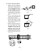
Figure 3
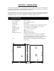
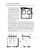
The Model 9150 operator is designed so that it can be installed in any of the mounting positions
shown below. Once the mounting position has been determined, the chain idlers must be adjusted to
accommodate the mounting position chosen before the operator is mounted to the pad or post. The
idlers are factory set for the front, pad mount position. (Note: Rear and center position, and post-
mounted operators require additional hardware not supplied with the operator).
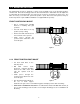
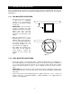
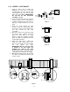
FRONT POSITION PAD MOUNT
•
This is considered the standard
method of installing slide gate
operators.
•
Set both chain idlers in the top
position (factory setting).
•
Remove the TOP chain knockouts
from each side of the operator.
•
Chain passes through the
operator and is attached to each
end of the gate.
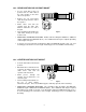
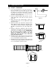
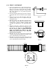
1.2.2 FRONT POSITION POST MOUNT
•
Set both chain idlers in the
bottom position.
•
DO NOT remove chain
knockouts. Using this mounting
method, the chain enters and
exits the operator from the
bottom.
•
Chain passes through the
operator and is attached to each
end of the gate.
•
This mounting method allows for
the use of chain support
attached to the gate. This is useful with long gates and helps prevent chain “stretching.”
•
ADDITIONAL HARDWARE REQUIRED: Post Mount Base Plate P/N 2600-495 and two (2)
6” x 6” steel mounting post at least three feet in length. Mounting post are not available from
DoorKing.
1.2 MOUNTING POSITIONS
Figure 2