DLE-61 Operator’s Manual Specifications Displacement: Performance: Idle Speed: Ignition Style: Recommended Propellers: Sparkplug Type: Diameter × Stroke: Compression Ratio: Carburetor: Weight: ™ 1 © 2014 Hobbico®, Inc. Fuel: 60cc 3.66 cu in 6 HP/7,500 RPM 1,400RPM Electronic Ignition 22x10,23x8,23x10,24x8 NGK CM6 (Gap) 0.018in.– 0.020 in. [0.45mm – 0.51mm] 1.85 in(47mm) x .98 in(35mm) 10.5: 1 DLE with Manual Choke Main Engine – 2.8 lb [1273g] Mufflers – 3.9oz [110g] Electronic Ignition – 3.
Parts List (1) DLE-61 Gas Engine with DLE Carburetor (1) CM6 Spark Plug with Ignition Wire Spring (1) Muffler w/Gasket (2) 5x20mm SHCS (muffler mounting) (1) Electronic Ignition Module w/ Additional Tachometer Lead (4) 68mm Engine Mounting Standoffs (8) 5x20mm SHCS with 5mm washers (engine mounting) (4) 5x40mm SHCS with 5mm Lock Washers & Flat Washers (propeller mounting) (1) Silicone Pick-up Wire Cover / Ignition Wire Cover (1) Red Three Pin Connector Lead w/ Pig Tail (for ignition switch) (2) Three Pin C
● ● ● ● ● ● ● ● ● ● ● ● ● ● 3 back to the engine and serious damages may occur during the break-in period. Break-in should be considered about the first 3-5 gallons you run through the engine. For your safety and the safety of others, please do not stand in front of or in line with the propeller when the engine is running. Keep onlookers away from the running engine, especially small children. Always use a balanced spinner and a balanced propeller.
● ● ● ● ● ● ● this by running the engine at idle until it quits by running out of fuel. Keeping gasoline inside the carburetor over an extended period of time will damage the diaphragm valve and clog passages inside the carburetor. Because the carburetor is more complicated than those used in glow engines, keep the fuel clean by using a fuel filter. Use a filter intended to be used with gasoline engines. Metal filters intended for glow engines are too coarse and will not screen out finer particles.
Installation Instructions Prepare the engine for installation 1. Check to see that all screws and bolts are tight. Check carefully for any cracks, broken, or missing parts. Tighten or replace any damaged or missing parts before proceeding. 2. Install the silicone wire cover over the pick up lead coming from the motor (cut the excess silicone wire cover) and connect the lead to the pick–up lead from the Electronic Ignition Module. Secure the connection with the included three pin connector securing clip.
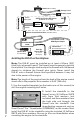
4. Connect the ignition module battery to the kill switch. Any 4.8-8.4V, 1000 mAh and above capacity battery will work well for this. Use heat shrink tubing to secure this connection. Optional: Install the TX activated gas engine kill switch (DLEG9205) between the manual on/off switch and the ignition as shown above. This is especially important during the starting sequence as it requires the manual on/off switch to be in the ON position before ignition can occur.
Switch (Not included) Charge Lead Battery Lead Ignition Battery Lead OPTO Gas Engine Kill Switch LED (DLEG9205, not included) KILL SWITCH Rx Ignition Rx Batt Lead Ignition Control Switch Wire (To On/Off Switch) Tachometer Lead/ RPM Signal Output Ignition Wire (To Spark Plug) Pick-Up Sensor Wire (To Sensor On Engine) OPTIONAL ELECTRONIC IGNITION SYSTEM Tachometer (Not included) DLEG5525 Installing the DLE-61 on Your Airplane Note: The DLE-61 must be installed on at least a 9.
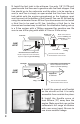
3. Install the fuel tank in the airframe. Use only 1/8" [3.175 mm] gasoline-safe fuel lines and a gasoline safe fuel tank stopper. One line should go to the carburetor and the other is to be used as a vent (a vent line is simply an open ended fuel line from the fuel tank which exits the engine compartment or the fuselage; most vent lines exit at the bottom of the firewall).
6. Install the choke servo (optional) at least 305mm [12"] away from the engine. Be sure to use a non-metallic linkage. 7. Install the ignition module securely in the airplane forward area. It is recommended that a thin piece of foam rubber is placed between the module and the mounting surface and that Velcro™ strap is used to hold the module in place. 8. Secure any unsecure connection with heat shrink tubing. (Not included.) 9. Connect the ignition wire from ignition module to the spark plug. 9 10.
11. Plug the smoke fitting on the muffler with a segment of fuel tubing and an 8-32 screw (not included). 12. Cut all necessary clearance, carburetor adjustment, cooling, and exhaust holes in the cowl. 13. Ensure the sensor wire is supported as close to the sensor pickup as possible. Flight loads may cause stress and damage to the wire where it enters the sensor body. 14. Make sure the cowl is secured to the airplane and that the spinner to cowl clearance is at least 3.2mm [1/8"].
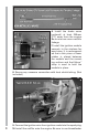
4. Place the propeller on the crankshaft at the 1 o’clock position. 5. Mark the location of one of the outer holes while the propeller is in the top of the compression stroke position. Use a Dead Center Hole Locator (GPMR8130) to center and start the hole. 6. Remove the propeller from the engine and drill the outer hole on the drill press using a #35 drill bit as a pilot hole. Next use a #5 (.2055” /5.21mm) drill bit to finish the hole.
8. Drill the remaining three holes in the propeller. In order to achieve a clean opening on both sides of the propeller, drill only half way through the propeller with the finishing drill bit. Then flip the propeller over and drill completely through the hole. 9. Mount the propeller to the engine using the 5x40mm SHCS with 5mm lock washers and flat washers. Be sure to use threadlocker. Starting Procedures There are two recommended ways to start the DLE-61: A.
10. After starting, let the engine idle for 30 to 45 seconds. Open and close the throttle slowly until the engine runs smoothly at idle and at full throttle. Acceleration should also be smooth. If acceleration is not smooth adjustments to the carburetor may be necessary. (See Adjustment of the Engine on page 14.) 11. If your engine does not start, repeat steps 6 through 10. B. Electric Starter Starting 1. A 24 volt electric starter is recommended to start the DLE-61.
Engine Troubleshooting If your engine fails to start after the preceding starting procedures please check the following.
Adjustment of the Engine Each DLE Engine has been factory preset. However, elevation changes will influence the performance of the carburetor. To obtain optimum output of the engine, slight adjustment of the carburetor maybe necessary. Also, for safety reasons do not make adjustments to the carburetor while the engine is running. Engine Functions and Adjustments 1. Choke Control (the choke should be used when the engine is cold) 2. Idle Adjustment Screw (adjust the idle speed)/Throttle Stop 3.
High Speed Needle Adjustment Turning the High-Speed Needle (No.5) clockwise will lean the fuel/air mixture at high speeds. Turning the High-Speed Needle (No.5) counter-clockwise will richen the fuel/air mixture at high speeds. (The default or factory setting of the High-Speed Needle is as follows; turn the needle to the fully stop/closed position and then open the needle 1.5 turns). It is recommended that the HighSpeed Needle be adjusted by the use of a tachometer to obtain maximum speed.
Problem 1. Engine stops at full throttle. 2. Engine hesitates when accelerated rapidly. 3. The engine will not come up to full rpm at full throttle. Solution The high-speed needle valve “H” is too lean. Open it 1/8 of a turn and try again. Problem 1. The engine does not reach full rpm. 2. Carbon build-ups appear consistently on your spark plug. Solution The high-speed needle valve “H” is too rich. Close it 1/8 turn and try again.
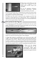
Optional Mini Tachometer An optional DigitalTachometer (DLEG5525) is available that can be directly connected to the ignition and display the RPMs of the engine.This unit can be installed on the aircraft or used to spot check the Engine RPMs. Do not install or uninstall the Digital Tachometer while the engine is running. Many of the DLE Ignition modules have an addition lead to plug into the optional tachometer.
Warranty Information The DLE-61 has a two year limited warranty through Hobby Services beginning at date of purchase. Contact Us Hobby Services 3002 N. Apollo Drive Suite #1 Champaign, Il 61822 Ph: 217-398-0007 Fax: 217-398-7721 E-mail: hobbyservices@hobbico.com Web address: www.hobbyservices.com 3.54 in. [90 mm] 2.64 in. [67 mm] 2.83 in.
4.96 in. [126 mm] 6.77 in. [172 mm] 21 2.68 in.
1 2 3 4 31 5 8 19 22 21 20 23 24 25 30 6 7 26 27 9 28 5 29 10 15 34 11 14 12 13 16 17 18
Replacement Parts Mfg Stock No.
DLE-61 Mounting Pattern 2.83 in. [ 72 mm] 2.64 in. [67 mm] 3.54 in.