POMPE DOSATRICI SERIE DLS NORME DI INSTALLAZIONE, USO E MANUTENZIONE ■ DLS SERIES METERING PUMPS OPERATING INSTRUCTIONS AND MAINTENANCE NORMES D’INSTALLATION, EMPLOI ET ENTRETIEN ■ BOMBAS DOSIFICADORAS SERIE DLS ENGLISH ■ POMPES DOSEUSES SERIE DLS ESPAÑOL FRANCAIS NORMAS PARA LA INSTALACIÓN, USO Y MANTENIMIENTO UNI EN ISO 9001 - 9190.
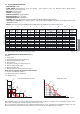
INDEX pag. 28 28 28 28 28 29 29 2.0 -DLS SERIES METERING PUMPS 2.1 - OPERATION 2.2 - COMMON FEATURES 2.3 - LIQUID ENDS MATERIALS 2.4 - DESCRIPTION OF THE TABLE 30 30 30 31 31 3.0 - INSTALLATION 3.1 - INJECTION VALVE INSTALLATION DIAGRAM 3.2 - SERVICE CONNECTOR WIRING DIAGRAMS AND FUNCTIONS 32 33 34 4.0 - MAINTENANCE 35 5.0 - HOW TO OPERATE WHEN DOSING SULPHURIC ACID 35 6.0 - TROUBLE-SHOOTING COMMON TO DLS SERIES 6.1 - MECHANICAL FAULTS 6.2 - ELECTRICAL FAULTS 36 36 36 7.
1.0 - HINTS AND WARNINGS Please read the warning notices given in this section very carefully, because they provide important information regarding safety in installation, use and maintenance of the pump. • Keep this manual in a safe place, so that it will always be available for further consultation. • The pump complies with EEC directives No.89/336 regarding "electromagnetic compatibility" and No.73/23 regarding "low voltages", as also the subsequent modification No.93/68. N.B.
1.5 - TOXIC AND/OR DANGEROUS LIQUID DOSAGE To avoid risk from contact with the hazardous liquids or toxic fumes, always adhere to the notes in this instruction manual: • Follow the instructions of the dosing liquid manufacturer. • Check the hydraulic part of the pump and use it only if it is in perfect condition. • Use only the correct materials for the tubing, valves and seals to suit the liquid to be dosed; where possible shield the tubing with PVC conduit.
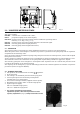
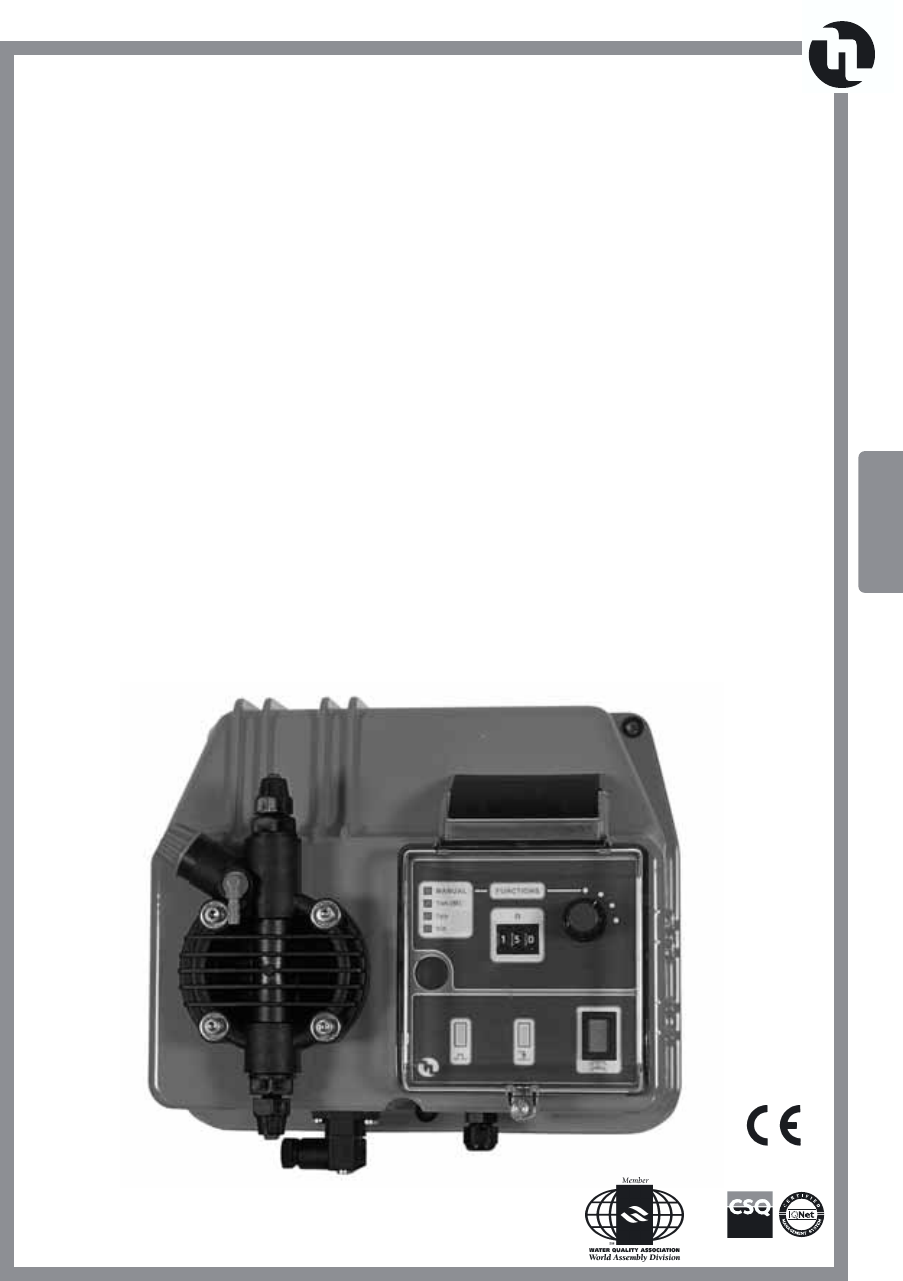
Fig. 1 2.0 - DLS SERIES METERING PUMPS This series include: DLS-MA: constant flow “manual/on-off” mode; DLS-F: proportional pump to an external pulse; DLS-VFT: microprocessor proportional pump with four different operating modes: manual, (1 x n - M), (1 x n), (1 : n); DLS-CC: microprocessor proportional pump based for external mA signal. DLS-PH: metering pump with integral pH meter; DLS-RX: metering pump with integral Redox meter; 2.
2.3 - LIQUID ENDS MATERIALS - DIAPHRAGM: PTFE - PUMP HEAD: Polypropylene (PVC for 05-20), upon request: PVC, 316 Stainless Steel, PTFE. Stroke Adjustment: PVC pump head - NIPPLES: polypropylene - FILTER: polypropylene - INJECTION NIPPLE: polypropylene - SUCTION HOSE: PVC - flexible - DISCHARGE HOSE: polyethylene - VALVES: “lip”type viton upon request available in EPDM (Dutral), NBR, Silycon. - “Ball Check” VALVES upon request type in SS 316 and Glass PYREX. Available with Spring Return and “KALRETZ”Valve.
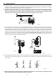
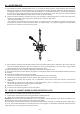
3.0 - INSTALLATION a. - Install the pump in a dry place and well away from sources of heat and, in any case, at environmental temperatures not exceeding 40°C. The minimum operating temperature depends on the liquid to be pumped, bearing in mind that it must always remain in a liquid state. b. - Carefully observe the regulations in force in the various countries as regards electrical installations (Fig.4).
Whenever the pump is dismantled from the process plant, you will be well advised to replace the caps on the connectors to avoid residual liquid being spilled. Before attaching the delivery hose to the plant, prime the metering pump by going through the sequence shown in Fig. 8. Before finalizing the installation of the discharge hose, make sure that the pump strokes will not cause it to move and bump into rigid bodies.
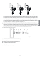
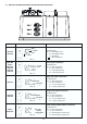
3.2 - SERVICE CONNECTOR WIRING DIAGRAMS AND FUNCTIONS Pump Model Female service connector wire assembly Relay service output connection N.C. Common DLS-PH DLS-RX Configuration: Pin 1 = Normally open “ 2 = Normally closed “ 3 = Common = No connection N.O. Pos. 1 DLS-MA DLS-F DLS-VFT DLS-CC DLS-PH DLS-RX Functions and technical informations Level probe connection Configuration: Pin 1 = No connection “ 2 = No connection “ 3 = Level probe wire “ 4 = Level probe wire To level probe Pos.
4.0 - MAINTENANCE ENGLISH 1. Periodically check the chemical tank level so as to avoid the pump operates without liquid. This would not damage the pump, but may damage the process plant due to lack of chemical. DLS series dosing pumps are all supplied with level control setting. The level switch is not included therefore to be ordered separately. Level control stops pump operation once the level into the chemical is lower then the level switch,activating a L.E.D.
6.0 - TROUBLE-SHOOTING COMMON TO DLS SERIES 6.1 - MECHANICAL FAULTS As the system is quite robust there are no apparent mechanical problems. Occasionally there might be a loss of liquid from the nipple because the tube nut has loosened, or more simply the discharge tubing-has broken. Very rarely there may be losses caused by the breakage of the membrane, or by the membrane seals in which case they have to be replaced by disassembling the four screws of the pump head fig.
Fig. 12 7.0 - MANUALLY OPERATED METERING PUMP DLS-MA Flow can be controlled manually by setting the pump pulse rate by means of a potentiometer. Pulse adjustable from 0 to 100 %. A Frequency switch reduces of 1/5 the scale of the flow potentiometer consequently the number of injections per minute for accurate control of low outputs 7.
DLS-MA Fig. 14 7.3 - PUMP CONTROLS 1 - ON/OFF light switch “green” 2 - Level L.E.D. “yellow” 3 - Pulse L.E.D. “red” 4 - 20% flow scale read out. 5 - Twin scale adjustment 0-100% - 0-20% 6 - 100% flow scale read out 7 - Flow rate adjustment 7.4 - PUMP CONTROLS DESCRIPTIONS Switch 1 turns power on. Turn knob 7 to increase flow and pump impulses: max flow at 100%. A dual frequency switch reduces of 20% the flow rate scale adjustment: 20% and 100% scale are indicated by two L.E.D. 7.
8.0 - VOLUMETRIC PROPORTIONAL DOSING PUMP Pump models: DLS-F and DLS-VFT. In this series the pump is controlled by pulses emitted from a w.meter reed contact (K). The number of pulses is proportional to the water flow point where the flow meter is installed. External pulses reach the pump through the w.meter connector (F) and by a specific adjustment will inject into the pipeline an amount of additive proportional to the liquid that flows into the line. ENGLISH DLS-F Fig. 15 8.
DLS-F Fig. 17 8.1.3 - PUMP CONTROLS 1 - ON/OFF light switch “green” 2 - Level L.E.D. “yellow” 3 - Pulse L.E.D. “red” 4 - Water meter mode indicator L.E.D. 5 - Proportional/Manual mode button 6 - Manual mode indicator L.E.D. 7 - Frequency adjustment (manual). For flow rates and technical data see table and diagrams. 8.1.4 - DLS-F PUMP CONTROL DESCRIPTION (Fig. 17) • ON/OFF SWITCH (1) Main power supply • GREEN L.E.D. ON Power supply ON • RED L.E.D. ON (3) Shows the pump pulse frequency • MANUAL /W.
DLS-F 8.1.6 - DLS-F PUMP ELECTRICAL FAULTS ❶ GREEN LIGHT SWITCH (1) ON, RED L.E.D. (3) OFF; THE PUMP DOESN’T PULSE A. Check the W. METER index turning condition; check that SELECTOR 5 is positioned on W. METER. B. Position SELECTOR 5 on MANUAL and % FLOW knob 7 at 50%. The pump pulse is regular: position SELECTOR 5 on W. METER and disconnect the pump from the impulse transmitter cable F then make a contact between the two side pins in the pump connection. (Section 3.2, pos.
DLS-VFT Fig. 18 8.2 - PROPORTIONAL DOSING PUMP TO AN EXTERNAL PULSE This pump incorporates a microprocessor unit providing for different operating modes: Manual 1 x n (M) 1xn 1:n For the description of each function, see the following page 8.2.1 - ACCESSORIES • 1 flexible PVC suction hose, transparent crystal type, length 2 m; • 1 semirigid polyethylene hose, white, length 2 m; • 1 injection valve 3/8 BSP m; • 1 filter; • 1 instructions/operating booklet. 8.2.2 - TYPICAL INSTALLATION (Fig.
DLS-VFT 8.2.3 - DLS-VFT PUMP CONTROLS (Fig. 20) 1 - ON/OFF light switch “green” 2 - Level L.E.D. “yellow” 3 - Pulse L.E.D. “red” 4 - Function L.E.D. 5 - Pulse selector 6 - Functions selector For flow rates and technical data see table and diagrams. Fig. 20 MODE 1 / Manual: The pump dispenses at a set frequency, which can be selected by the operator. The figure given on the selector 5 indicates the number of injections the pump supplies in a minute. Maximum 100 injections per minute are possible.
DLS-VFT 8.2.5 - DLS-VFT PUMP ELECTRICAL FAULTS ❶ GREEN LIGHT SWITCH (1) ON, RED L.E.D. (3) OFF; THE PUMP DOESN’T PULSE A. Check the W. METER index turning condition; check that SELECTOR 6 is positioned on W. METER (1 x n (M), 1 x n, 1 : n). B. Position SELECTOR 6 on MANUAL and SELECTOR 5 at 50. The pump doesn’t pulse: contact manufacturer customer service, dealer or distributor. The pump pulse is regular: position SELECTOR 6 on W.
DLS-CC 9.0 - PROPORTIONAL PUMP REGULATED BY A CURRENT SIGNAL The DLS-CC dosing pump is a microprocessor unit suitable for operation in proportion to a “mA” input signal. Connected to a transmitter / indicator instrument or other device which supplies a modulated current signal from 0 to 20 mA, the pump pulse frequency will be proportional to the mA signal received: higher the signal higher the pump flow. The pump can be adapted for inverse operation: the higher signal corresponds to the lowest flow.
DLS-CC Fig. 23 9.4 - DLS- CC PUMP CONTROLS (Fig. 23) 1 - ON/OFF light switch “green” 2 - Level L.E.D. “yellow” 3 - Pulse L.E.D. “red” 4 - Functions selection button 5 - Functions L.E.D. 6 - Decrease button 7 - mA L.E.D. 8 - Functions selector (mA/manual pulse) 9 - Stroke L.E.D. 10 - Display 11 - Enter button 12 - Increase button. 9.5 - CALIBRATION Switched On (1), the pump is automatically in the “Meter” function, this is shown in the display imp/min.
Serie DLS - Series
VALVOLE - VALVES Valvole di iniezione complete di raccordo Complete injection valves VALVOLA INIEZIONE STD. fino a 20 l/h STD. INJECTION VALVE up to 20 l/h VALVOLA INIEZIONE 1/2” 50 l/h 1/2” 50 l/h INJECTION VALVE VALVOLA INIEZIONE 90° fino a 20 l/h 90° INJECTION VALVE up to 20 l/h VALVOLA INIEZ.
Corpo pompa completo: P.P. - PVC - Acciaio inox - PTFE Complete Pump Head: P.P.