
Operating instructions
• 34 •
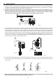
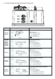
Pump Model Female service connector wire assembly Functions and technical informations
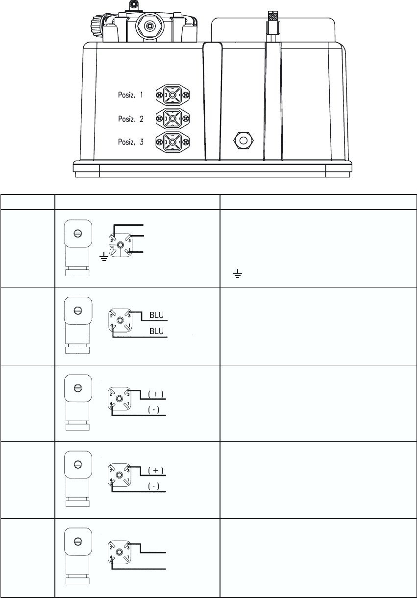
Relay service output connection
Configuration:
Pin 1 = Normally open
“ 2 = Normally closed
“ 3 = Common
= No connection
Level probe connection
Configuration:
Pin 1 = No connection
“ 2 = No connection
“ 3 = Level probe wire
“ 4 = Level probe wire
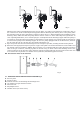
Input mA signal connection
Configuration:
Pin 1 = No connection
“ 2 = No connection
“ 3 = (+) mA signal wire
“ 4 = (-) mA signal wire
Pos. 3
Output mA signal connection
Configuration:
Pin 1 = No connection
“ 2 = No connection
“ 3 = (+) mA signal wire
“ 4 = (-) mA signal wire
Pos. 3
Input
mA signal
Uscita
segnale
in mA
Pos. 2
Pos. 1
DLS-PH
DLS-RX
DLS-PH
DLS-RX
DLS-MA
DLS-F
DLS-VFT
DLS-CC
DLS-PH
DLS-RX
DLS-CC
Pulse emitting Water Meter connection
Configuration:
Pin 1 = No connection
“ 2 = No connection
“ 3 = Water Meter signal wire
“ 4 = Water Meter signal wire
Pos. 3
DLS-F
DLS-VFT
3.2 - SERVICE CONNECTOR WIRING DIAGRAMS AND FUNCTIONS
N.C.
N.O.
Common
To level
probe
Output
mA signal
To pulse
emitting
Water Meter