IPPC-7158 Series 15" XGA TFT LCD Industrial Panel PC with 14 x ISA/PCI/ PICMG Slots, Passive Backplane and Membrane Keypad User Manual
Copyright Notice This document is copyrighted 2008, by Advantech Co. Ltd. All rights are reserved. Advantech Co., Ltd. reserves the right to alter the products described in this manual at any time without notice. No part of this manual may be reproduced, copied, translated or transmitted in any form or by any means without the prior written permission of Advantech. Information provided in this manual is intended to be accurate and reliable.
FCC Class A Note: This equipment has been tested and found to comply with the limits for a Class A digital device, pursuant to part 15 of the FCC Rules. These limits are designed to provide reasonable protection against harmful interference when the equipment is operated in a commercial environment. This equipment generates, uses, and can radiate radio frequency energy and, if not installed and used in accordance with the instruction manual, may cause harmful interference to radio communications.
Packing List Before setting up the system, check that the item is among those listed below and is in good condition. If your Workstation does not match any of those below, please contact your dealer immediately.
Additional Information and Assistance Step 1. Visit the Advantech web site at www.advantech.com where you can find the latest information about the product. Step 2. Contact your distributor, sales representative, or Advantech's customer service center for technical support if you need additional assistance.
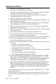
Safety Instructions 1. Read these safety instructions carefully. 2. Keep this User's Manual for later reference. 3. Disconnect this equipment from any AC outlet before cleaning. Use a damp cloth. Do not use liquid or spray detergents for cleaning. 4. For plug-in equipment, the power outlet socket must be located near the equipment and must be easily accessible. 5. Keep this equipment away from humidity. 6. Put this equipment on a reliable surface during installation.
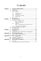
Contents Chapter Chapter 1 General Information ....................................... 2 1.1 1.2 Introduction ....................................................................... 2 Specifications .................................................................... 3 1.3 Dimensions........................................................................ 5 1.2.1 1.2.2 1.2.3 1.2.4 1.2.5 2 System Setup.................................................... 8 2.1 A Quick Tour of IPPC-7158 ................
IPPC-7158 User Manual viii
CHAPTER 1 General Information This chapter gives background information on the IPPC-7158 series Sections include: • Introduction • Specifications • Dimensions
Chapter 1 General Information 1.1 Introduction The IPPC-7158 features a 15" TFT LCD and 14 expansion slots for PCI, PICMG and ISAand an ATX industrial backplane to support CPU cards. The IPPC-7158 also provides many powerful features such as detahable front panel, front-accessible USB port, 53 membrane key & touch pad with two mouse buttons, 6 OSD control keys, NEMA4/IP65 compliant front panel, and optional analog resistive touchscreen (USB Interface).
1.2 Specifications 1.2.1 General • Button Control: Membrane Keypad 1: 43 operating keys Membrane Keypad 2: 10 programmable macro function keys • Certifications: BSMI, CCC, CE, FCC • Cooling System: 1 x 49 CFM fan w/50,000 hrs MTBF • Dimensions (W x H x D): 482 x 354.8 x 162 mm (18.97" x 13.96" x 6.37") • Disk Drive Bay: Supports 1 x FDD, 1 x 3.
1.2.3 LCD Display • Backlight Life: 60,000 hrs • Contrast Ratio: 500 : 1 • Display Size: 15" • Display Type: XGA TFT LCD • Luminance: 250 cd/m2 • Max. Colors: 16.2 M (RGB 6-bit + FRC data) • Max. Resolution: 1024x768 • OSD Control: ON/OFF, Brightness down, up (behind the front panel) • Viewing Angle (H/V°): 140/120 1.2.
1.3 Dimensions IPPC-7158A 17 4 1 + M3 8 5 2 0 9 ___ __ 7 M1 M2 ” / 6 3 _ = M4 Esc Delete M5 Tab PgDn Back Space M6 Ctrl M7 M8 Enter Alt Left PgUp Shift Space Right M9 M10 F1 F2 F3 F4 F5 F6 F7 F8 F9 F10 F11 F12 Figure 1.
IPPC-7158 User Manual 6
CHAPTER 2 System Setup This chapter details system setup for the IPPC-7158 Series.
Chapter 2 System Setup 2.1 A Quick Tour of IPPC-7158 Before you start the computer, please follow these procedures to set up the system. 1. Check and adjust jumpers on motherboard (optional by each CPU card) 2. Install SDRAM 3. Install CPU & CPU Cooler 4. Install add-on cards 5. Connect the wires, cables and accessories 6. Mount the computer 7. Program the BIOS settings 8. Install an operating system. Warnings 1. The IPPC-7158B only includes the chassis and B/P.
Figure 2.1: Open View Figure 2.
2.1.1 USB Ports An external USB device may be connected to the system via the USB ports located on the right side of the system unit and also could access from 1 USB port on the front panel of IPPC-7158. 1. Connect the external device to the system. 2. The USB ports support hot plug-in connection. You should install the device driver before you use the device. Figure 2.3: Opening the Front USB Port Cover 2.1.
2.1.3 System On/Off The IPPC-7158 has 1 system on/off switch, located inside the chassis.
2.2 Installing Optional Disk Drives The IPPC-7158 provides spaces for one 3.5" hard disk drives, one CDROM drive, & one 3.5" floppy disk drive within the chassis. Front-facing FDD & CD-ROM have already been installed. You can access them after opening the front LCD panel. Below is the procedure of installing HDD and CD-ROM: 1. Unscrew the 3 screws and 4 screws on the side of the case to remove the HDD Drive Bay 2. Unscrew the 4 Screws on the bottom of the drive bay to separate the 2 parts. 3.
CHAPTER 2 3 Touchscreen This chapter contains information on the touchscreen, its installation and configuration.
Chapter 3 Touchscreen 3.1 Introduction The IPPC-7158 Series’ optional touchscreen uses advanced 8-wire resistive technology. It provides more accurate sensing capacity than other technologies. The touchscreen is specially designed for tough industrial environments, and has been approved to FCC Class B standards. 3.2 Touchscreen Driver Installation & Configuration The touchscreen of IPPC-7158 is controlled by USB interface and has drivers for Linux, Windows 2000, Windows XP, Windows Vista and Windows CE.
Appendix A LCD Specifications and Selection Settings
Appendix A LCD Specifications A.1 IPPC-7158 LCD Specifications Model IPPC-7158 Display 15" TFT LCD Max. resolution 1024 x 768 Colors 16.2M colors (RGB 6-bit + FRC data)/262k(RGB 6-bit) selectable Dot pitch (mm) 0.297 (per one triad) x 0.297 Viewing angle 140 (H), 120 (V) Luminance 250 cd/sq meter Viewing area 304.128 (H) x 228.096 (mm Power consumption 10.7 W (Typ.) @ 6.0mA (Gray Bar Pattern) Operating temperature 0 ~ 50°C Storage temperature -20 ~ 60°C Backlight MTBF 60,000 hours .
Appendix Pin Assignments B
Appendix B Pin Assignments Connector Description ISA1, ISA2 ISA Slot ISA3, ISA4 PICMG connector (PCI Slot is PICMG1, PICMG2) PICMG1, PICMG2 PICMG connector PPCI1~PPCI3 32 bit / 33 MHz PCI slot SPCI4~SPCI10 32 bit / 33 MHz PCI slot KB1 KB-In or KB-Out connector (90’P) KB2, KB3 KB-In or KB-Out connector (180’P) KB4 KB-Out, external connector AT1 Main AT Power connector supply +/-5V, +/-12V ATX1 Main ATX Power connector supply +3.
B.1 Connector Pin Definitions Pin Definition 1 +3.3V 2 +3.3V 3 COM 4 +5V 5 COM 6 +5V 7 COM 8 Power OK 9 +5VSB (Standby) 10 +12V 11 +3.
AT1 Pin Name 1 NC 2 +5V 3 +12V 4 -12V 5 GND 6 GND 7 GND 8 GND 9 -5V 10 +5V 11 +5V 12 +5V BIG1 Pin Name 1 +12V 2 GND 3 GND 4 +5V CN1 Pin Name 1 PS-ON 2 GND 3 5VSB IPPC-7158 User Manual 20
CN2 Pin Name 1 5VSB 2 GND 3 GND 4 -5V 5 +5V 6 +3.
B.
Appendix C Keyboard Translator
Appendix C Keyboard Translator C.1 Overview The keyboard translator is an interface that switches the signal from the membrane keypad to the standard AT keyboard. There are six connectors on the board. On top of the board, there are two connectors linking two flat cables to the membrane keypad (as shown in Fig. 4-3). On the side of the board, there are four connectors. The figure below shows the keyboard translator & the cable connection for macro keys programming details.
Caution: Keyboard Translator(KBT-2002) can't be programmed through the USB keyboard. The step of programming the Macro Key(M1~M10) on the front panel: 1. Open the front panel door, use a PS/2 keyboard connect to the reserved external keyboard terminal of KBT-2002 which on the back of front panel (see figure below). 2. Boot up the system and enter the BIOS, check & make sure the USB function is disabled.
C.3 Keyboard Translator Maintenance (KBT-2002) Below is the procedure of replacing the keyboard translator while needed: 1. Switch off the power, and detach the main power cord. 2. Unscrew the screws on front panel and open the front panel door of IPPC-7158. 3. The Keyboard Translator will be located on the back of the front panel, behind the mylar protect. (Seebelow) 4. Unscrew the screws on the mylar and remove it. 5. Remove the keypad connector protective bracket. 6.