
Specifications

G121SN01 V4 rev. 1.4
P
age 19/24
G
121SN01 V4
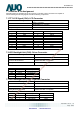
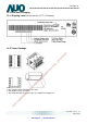
7. Connector & Pin Assignment
Physical interface is described as for the connector
on module. These connectors are capable of
accommodating the following signals and will be following components.
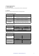
7.1 TFT-LCD Signal (CN1): LCD Connector
Connector Name / Designation Signal Connector
Manufacturer
STM or compatible
Connector Model Number
MSB240420-E or compatible
Adaptable Plug
P240420 or compatible
Pin No. Symbol Pin No. Symbol
1 VDD 2 VDD
3 GND 4 SEL68
5 RIN0- 6 RIN0+
7 GND 8 RIN1-
9 RIN1+ 10 GND
11 RIN2- 12 RIN2+
13 GND 14 CLKIN-
15 CLKIN+ 16 GND
17 RIN3- 18 RIN3+
19 RSV 20 NC/GND
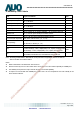
7.2 LED Backlight Unit (CN2): Driver Connector
Connector Name / Designation Lamp Connector
Manufacturer ENTERY or compatible
Connector Model Number 3808K-F05N-02R or compatible
Mating Model Number H208K–P05N-02B or compatible
Pin No. symbol description
Pin1 VCC 12V input
Pin2 GND GND
Pin3 On/OFF 5V-ON,0V-OFF
Pin4 Dimming PWM
Pin5 NA
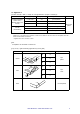
7.3 LED Backlight Unit (CN4): Light bar Connector
Connector Name / Designation Lamp Connector
Manufacturer ENTERY or compatible
Connector Model Number H208K–P03N-02B or compatible
Mating Model Number(CN3) 3808K-F03N-02R or compatible
Pin No. symbol description Color
Pin1 H LED anode Red
Pin2 L LED cathode White
Pin3 L LED cathode Black
AUO Confidential For DATAMODUL Internal Use Only / 2012/10/24
Data Modul AG - www.data-modul.com