
Specifications
G0
65VN01 V2 Ver. 1.2
14/24
G
065VN01 V2
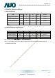
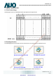
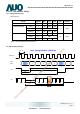
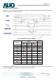
6.3 The Input Data Format
SEL68 = ”Low” or “NC” for 6 bits LVDS Input
SEL68 = “High” for 8 bits LVDS Input
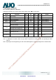
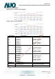
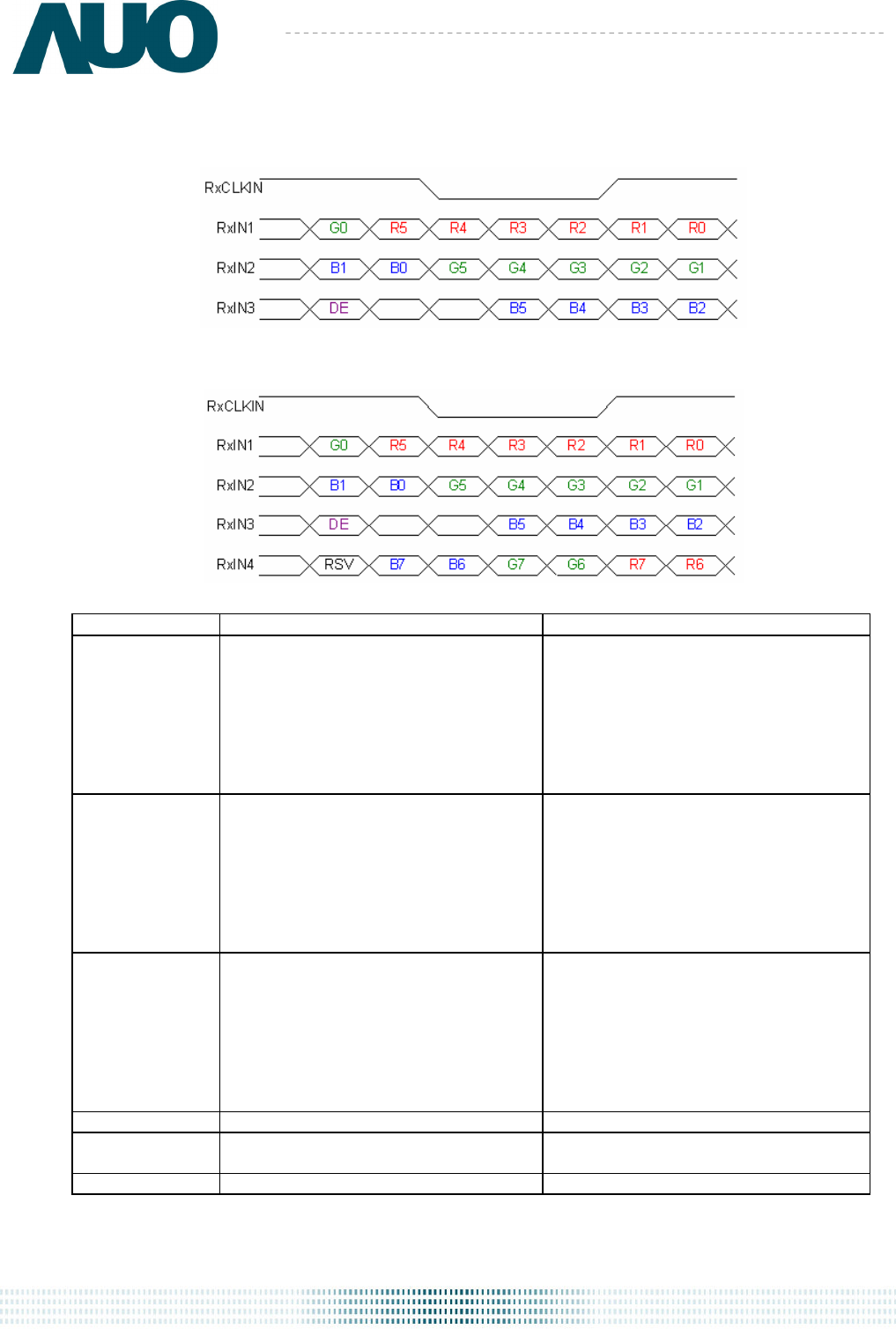
Signal Name Description Remark
R7
R6
R5
R4
R3
R2
R1
R0
Red Data 7
Red Data 6
Red Data 5
Red Data 4
Red Data 3
Red Data 2
Red Data 1
Red Data 0
Red-pixel Data
For 8Bits LVDS input
MSB: R7 ; LSB: R0
For 6Bits LVDS input
MSB: R5 ; LSB: R0
G7
G6
G5
G4
G3
G2
G1
G0
Green Data 7
Green Data 6
Green Data 5
Green Data 4
Green Data 3
Green Data 2
Green Data 1
Green Data 0
Green-pixel Data
For 8Bits LVDS input
MSB: G7 ; LSB: G0
For 6Bits LVDS input
MSB: G5 ; LSB: G0
B7
B6
B5
B4
B3
B2
B1
B0
Blue Data 7
Blue Data 6
Blue Data 5
Blue Data 4
Blue Data 3
Blue Data 2
Blue Data 1
Blue Data 0
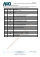
Blue-pixel Data
For 8Bits LVDS input
MSB: B7 ; LSB: B0
For 6Bits LVDS input
MSB: B5 ; LSB: B0
RxCLKIN LVDS Data Clock
DE Data Enable Signal
When the signal is high, the pixel data
shall be valid to be displayed.
RSV Reserved Signal “High” or “Low” is acceptable
Note 1: Output signals from any system shall be low or Hi-Z state when VDD is off.
AUO Confidential For DATAMODUL Internal Use Only / 2012/10/11
Data Modul AG - www.data-modul.com