V PANEL 104 / 121 / 150 / 170 / 190 User manual Rel. 08.2005 Ver.01 0-0096-3132 The German version of this manual is not available. Die deutsche Version ist nicht verfügbar.
V Panel 104 / 121 / 150 / 170 / 190 User Manual Manual History Date Aug.2005 Version 01 Changes First edition Kontron Embedded Computers GmbH Werner-von-Siemens-Str. 1 93426 Roding Phone: +49 9461 950 -0 Fax: +49 9461 950 -100 e-mail: sales@kontron.com Internet: http://www.kontron.com © Copyright Kontron Embedded Computers GmbH 2005.
Werner-von-Siemens Str.
V Panel 104 / 121 / 150 / 170 / 190 User Manual ence to radio or television reception, which can be determined by turning the equipment off and on, the user is encouraged to try to correct the interference by more of one or more of the following measures: 1. Reorient or relocate the receiving antenna 2. Increase the separation between the equipment and receiver. 3. Connect the equipment into an outlet on a circuit different from that to which the receiver is connected 4.
Werner-von-Siemens Str.1 D - 93426 Roding Tel: +49 9461 950 - 0 Fax: +49 9461 950 - 100 Table of contents Copyright .................................................................................................... 3 Trademarks ................................................................................................ 3 CE-Conformity ............................................................................................ 3 1. Introduction .........................................................
V Panel 104 / 121 / 150 / 170 / 190 User Manual 1. INTRODUCTION 1.1. APPROPRIATE USE The main purpose of the V Panel is the use and operation with 24VDC-powersources. The surrounding area of the Panel are dry rooms. The Panel is intended for industrial applications in machine and plant control engineering. The user is not entitled to change the system components or open the body without consultation to Kontron. 1.2 ITEM CHECKLIST Your Panel comes securely packaged in solid shipping carton(s).
Werner-von-Siemens Str.1 D - 93426 Roding Tel: +49 9461 950 - 0 Fax: +49 9461 950 - 100 Do not leave the Panel in an unconditional environment. Storage temperature above 70°C may damage the Panel. The opening on the enclosure are for air convection, protect the Panel from overheating. DO NOT COVER THE OPENINGS If the Panel is not in use for a long time, disconnect it from mains to avoid possible damage by transient overvoltage.
V Panel 104 / 121 / 150 / 170 / 190 2. User Manual OVERVIEW The Kontron V Panel computer is a high performance system. The compact design enables an integration even under the condition of very restricted spaces. Our 100% industiy capable, scalable Panel meet the highest requirements concerning shock, vibration and temperature resistance. The system also provides a high resistance under tough EMC conditions.
Werner-von-Siemens Str.1 D - 93426 Roding Tel: +49 9461 950 - 0 Fax: +49 9461 950 - 100 3. HARDWARE INSTALLATION Attention! The weight of the Panel is about 7kg Carry it on with both hands! The Panel of this type is developed to work in a control cabinet. Thereby it must be pointed that all the environmental conditions must be considered. When installing the Panel take care that there is enough area for ventilations on rear side. For details go to item housing dimensions.
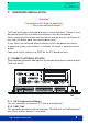
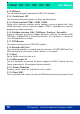
V Panel 104 / 121 / 150 / 170 / 190 User Manual 3.1.3 USB port This connector provides two external USB 2.0 interfaces 3.1.4 Parallel port LPT Use this port to connect a printer or other parallel devices. 3.1.5 Serial Interface COM1, COM2, COM3 Three serial interfaces enables you to connect a external device with 9 pin DSUB connector such as mouse or modem. COM2 is selectable as a input for programming fielbuscontroller. 3.1.
Werner-von-Siemens Str.1 D - 93426 Roding Tel: +49 9461 950 - 0 Fax: +49 9461 950 - 100 3.2 CONNECT INTERNAL DEVICES The panel provides additional functions which could be implemented in the system by adding cards or changing the configuration of your Panel. CF ETX CPU Module Fig. 3-2 http://www.kontron.
V Panel 104 / 121 / 150 / 170 / 190 Connector J3 J4 J6 J12 J13 J15 J16 J17 J18 J21 J24 J25 J26 J29 J30 J31/J32 J34 J36 User Manual Interface Serial port COM3 Serial port COM4 Backlight interface Advanced power button interface External battery connector Internal Fieldbus interface Floppy disk drive interface Secondary IDE Compact flash Primary IDE Connector UDMA33 IrDA/FIR connector PCI extension card PCMCIA Internal HDD power interface 4-5 wire Tochconnector DMC touchcontroller interface (option) Interna
Werner-von-Siemens Str.1 D - 93426 Roding Tel: +49 9461 950 - 0 Fax: +49 9461 950 - 100 3.3.4 Address range fielbus controller EC1 3.3.5 Fieldbus Contrl. SJ1000 Interrupt (optional) DIP4 OFF OFF ON ON OFF OFF ON ON DIP5 OFF ON OFF ON OFF ON OFF ON Interrupt request IRQ3 IRQ4 IRQ5 IRQ7 IRQ10 IRQ11 No fieldbus installed No interrupt 3.3.6 Fieldbus Contrl.
V Panel 104 / 121 / 150 / 170 / 190 OFF ON SW3 OFF Setting SW3 DIP1 OFF ON SW3 1 ON 3.3.11 Communication port to touchcontroller User Manual 1 Communication port COM COM1 COM4 3.3.12 Touch wire configurationr 3.3.13 Output configuration USB Port 0 Setting SW4 DIP1 OFF (default) ON SW4 OFF Touchtype 5 wire 4 wire ON Setting SW3 DIP2 OFF ON 1 USB Port 0 External Connector J22 Internal Connector J31 3.3.
Werner-von-Siemens Str.1 D - 93426 Roding Tel: +49 9461 950 - 0 Fax: +49 9461 950 - 100 4 SOFTWARE INSTALLATION 4.1 APPLICATION SOFTWARE AND OPERATING SYSTEM The panel is designed to work with different operating systems. To install operating system or application software follow the installation instructions of the software. 4.2 HARDWARE DRIVERS On preinstalled systems no drivers had to be installed by a technican or user.
V Panel 104 / 121 / 150 / 170 / 190 User Manual >>Start installation and set folder >>Choose your destination folder 16 © Copyright Kontron Embedded Computers GmbH
Werner-von-Siemens Str.1 D - 93426 Roding Tel: +49 9461 950 - 0 Fax: +49 9461 950 - 100 >>Choose display of touch icon in system tray >>Select installed touch controllers Value: 1 >>Select spread of touch on display Value line 1:“Whole Desktop” Value line 2:“Device1” http://www.kontron.
V Panel 104 / 121 / 150 / 170 / 190 User Manual >> Select controler type Value: DMC TSC-10 Series USB >> Installation Calibration To get the according touch function you had to calibrate the touch. To do this go to START/Programs/DMC/ Calibrate Do the calibration with a touch stick on the displayed arrows. Install ELO touch driver Installation procedure To start driver installation please go to the folder where the driver files are stored. Start driver installation by double click on file “SW500930.
Werner-von-Siemens Str.1 D - 93426 Roding Tel: +49 9461 950 - 0 Fax: +49 9461 950 - 100 >> Choose your destination folder to extract files >> Select touch type “USB touchsreen “ http://www.kontron.
V Panel 104 / 121 / 150 / 170 / 190 User Manual >>Confirm licence agreement >>Start touch calibration 20 © Copyright Kontron Embedded Computers GmbH
Werner-von-Siemens Str.1 D - 93426 Roding Tel: +49 9461 950 - 0 Fax: +49 9461 950 - 100 After complete installation and calibration of touch you find a new icon in the control panel to set additional features. 4.2.2 Install EC1 fieldbus driver Basically your system is perpared as one of the possible fieldbus interfaces. That means that the firmware of the controller inside is programmed, and the needed fieldbus module is mounted.
V Panel 104 / 121 / 150 / 170 / 190 User Manual >>Select your destination folder >> Choose your program description 22 © Copyright Kontron Embedded Computers GmbH
Werner-von-Siemens Str.1 D - 93426 Roding Tel: +49 9461 950 - 0 Fax: +49 9461 950 - 100 5. TECHNICAL DETAILS 5.1 MECHANICAL Features V Panel Model 104 121 Display size 10,4“ 12.1” Dimension 295 x 348 x 121mm 327 x 400 x 121mm panelmount HxWxD Front Bezel ALU or stainless steel optional Weight 6,6 kg 8 kg Protection class IP65 Front (NEMA 250 type 12 and 13) 150 15” 362 x 452 x 123mm 170 17” 390 x 465 x 130mm 190 19” 426 x 516 x 135mm 9,85kg 11,7kg 13,4kg 5.2 ELECTRONICAL Features Model Max.
V Panel 104 / 121 / 150 / 170 / 190 User Manual 5.3 ENVIRONMENT Features V Panel all models Temperature Operating: 0° to +50°C Storage: -25° to +70°C Humidity Operation: 5 to 95% non condensino Storage: 5 to 95% non condensing Cooling Fanless cooling concept Shock acc. DIN Operating: 15G, 11ms duration EN 60068-2-27 Storage: 50G, 11ms duration (half-sinus) Vibration acc.
Werner-von-Siemens Str.
V Panel 104 / 121 / 150 / 170 / 190 User Manual Power Connector PIN 1 2 3 1 3 Signal Name GND NC 24V IN RS232 Connector Signal Name DCD (Data Carrier Detect) RXD (Receive Data) TXD (Transmit Data) DTR (Data Terminal Ready) GND DSR (Data Set Ready) RTS (Request To Send) CTS (Clear To Send) RI (Ring Indicator) J34 PIN 3 4 Serial port COM3 , COM4 PIN 1 3 5 7 9 Signal Name DCD (Data Carrier Detect) RXD (Receive Data) TXD (Transmit Data) DTR (Data Terminal Ready) GND Backlight interface PIN 1 2 3 4 5
Werner-von-Siemens Str.1 D - 93426 Roding Tel: +49 9461 950 - 0 Fax: +49 9461 950 - 100 External battery connector PIN 1 3 5 7 9 11 13 15 17 19 21 23 25 27 29 31 33 Signal Name GND GND NC GND GND GND GND GND GND GND GND GND GND GND NC GND NC http://www.kontron.
PIN 1 3 5 7 9 11 13 15 17 19 21 23 25 27 29 31 33 35 37 39 41 43 28 Signal Name RESET# Data 7 Data 6 Data 5 Data 4 Data 3 Data 2 Data 1 Data 0 GND DRQ# IOW# IOR# IORDY ACK# IRQ ADDR1 ADDR0 CS0# Active# +5V GND PIN 2 4 6 8 10 12 14 16 18 20 22 24 26 28 30 32 34 36 38 40 42 44 1 2 Primary IDE Connector UDMA33 J18 Signal Name NC Data 11 Data 12 Data 13 Data 14 Data 15 CS1# NC IOR# IOW# VCC IRQ VCC M#/S (Compact Flash) NC RESET# IORDY REQ# ACK# Active# DIAG Data 8 Data 9 Data 10 GND 43 PIN 26 27 28 29 3
Werner-von-Siemens Str.1 D - 93426 Roding Tel: +49 9461 950 - 0 Fax: +49 9461 950 - 100 IrDA/FIR connector PIN 1 2 3 4 5 J21 Signal Name +5V NC IRRX GND IRTX PCI Edge card Master connector PIN A1 A2 A3 A4 A5 A6 A7 A8 A9 A10 A11 A12 A13 A14 A15 A16 A17 A18 A19 A20 A21 A22 A23 A24 A25 A26 A27 A28 A29 A30 A31 1 Signal Name NC +12V NC NC +5V INTA# INTC# +5V NC +5V (I/O) NC GND GND GNT1# RESET# +5V (I/O) GNT0# GND REQ2# AD30 +3.3V AD28 AD26 GND AD24 NC +3.
V Panel 104 / 121 / 150 / 170 / 190 PIN 1 2 3 4 5 6 7 8 9 10 11 12 13 14 15 16 17 18 19 20 21 22 23 24 25 26 27 28 29 30 31 32 33 34 Signal Name GND AD0_Data 3 AD1_Data 4 AD3_Data 5 AD5_Data 6 AD7_Data 7 C/BE0#_CE1 AD9_A10 AD11_OE# AD12_A11 AD14_A9 C/BE1#_A8 PAR_A13 PERR#_A14 GNT_WE INTX_READY_IREQ AVCC AVCCP CLK_A16 IRDY#_A15 C/BE2X_A12 AD18_A7 AD20_A6 AD21_A5 AD22_A4 AD23_A3 AD24_A2 AD25_A1 AD26_A0 AD27_Data 0 AD29_Data 1 RSVD_Data 2 CLKRUN_WP_IOCS16# GND Internal HDD power interface PIN 1 2 3 4 30 S
Werner-von-Siemens Str.
V Panel 104 / 121 / 150 / 170 / 190 User Manual 5.6.2 Fieldbus modules (optional) 5.6.2.1 Profibus module 5 1 9 PIN 1 2 3 4 5 6 7 8 9 6 female Signal Name NC NC RXD-P/TXD-M ISODE ISOLATET GND ISOLLATED +5V NC RXD-M/TXD-M NC 5.6.2.2 Canbus module 1 5 6 PIN 1 2 3 4 5 6 7 8 9 9 male Signal Name NC CANL ISOLATED GND NC NC NC CANH NC NC 5.6.2.
Werner-von-Siemens Str.1 D - 93426 Roding Tel: +49 9461 950 - 0 Fax: +49 9461 950 - 100 5.7 BLOCK DIAGRAM The diagram displayed below shows the main internal function blocks of the Panel.
V Panel 104 / 121 / 150 / 170 / 190 6. User Manual MAINTENANCE The Panel is designed and produced according to DIN EN ISO 9000:2000. One of the main development intentions was to minimice service requirements. As a result, with exception changing CMOS-Ram battery and cleaning, no great service is to do. In case off any error kindly note the remarks below. To analyze the error please check first all connections and configuration of the software. Don’t try to repair the hardware inside.
Werner-von-Siemens Str.1 D - 93426 Roding Tel: +49 9461 950 - 0 Fax: +49 9461 950 - 100 6.3.1 Return Material Authorization Numbers (RMA) Before send back the defective device please follow the hints below then request a RMA number from Kontron customer service. • Return only Kontron product specified on the RMA request. • Request a separate new RMA number for each Kontron product. • If we receive a shipment containing not authorized products, we may send it back.
V Panel 104 / 121 / 150 / 170 / 190 7. User Manual TROUBLESHOOTING 7.1 FAQ Please look to the online support at www.kontron.com 8. DISPOSAL In order to dispose your Panel, it must be removed from the plant and fully dismantled. Electronic part such as disc drives and circuit boards must be disposed of in accordance with national electronic scrap regulations. For details ask your local waste disposal department. 9. APPENDIX ILLUSTRATION CONTENTS Fig. 3-1 Connect external devices ....................