
User manual


http://www.kontron.com
33
Werner-von-Siemens Str.1
D - 93426 Roding
Tel: +49 9461 950 - 0
Fax: +49 9461 950 - 100
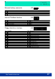
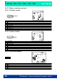
5.7 BLOCK DIAGRAM
The diagram displayed below shows the main internal function blocks of the
Panel.
ETX-Modul
LVDS
J7 und J35
CRT
J1
LAN
J22
USB 2/3
J32
PS/2 Mouse
J28
PS/2
Keyboard
J28
LPT1
J1
Floppy
J16
2nd LAN**
J37
EC1*
Fieldbus
PB, CAN
DeviceNET
J15
NVSRAM**
COM3
J3
Touch
J29 und J30
HDD
J18
Switchlogic
ISA-Bus PCI-Bus
PCMCIA**
J25
CF
J17
SJA1000*
* only SJA1000 or EC1 populated
Super I/O
COM4
COM3
IRDA
J21
COM1
J1
COM4
J4
COM1
COM2
J2
USB 0/1
J22 und J31
COM2
PCI-Riser
J24
Switchlogic
** optional populated
Watchdog**
U43
External interface
Internal interface
fig. 5-1