
User guide
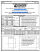
D-M-E CHILL VENT BY NGK Specification No. ME-080065-999(C)
VPS9999 Page 1 of 2
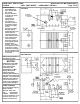
IMPORTANT SAFETY INFORMATION
BEFORE USING THIS PRODUCT
REFER TO IMPORTANT SAFETY INFORMATION AT MANUFACTURER’S WEBSITE:
http://www.ngkmetals.com/index.cfm/m/19
ADDITIONAL INFORMATION MAY BE FOUND AT:
http://www.osha.gov/dts/hib/hib_data/hib19990902.html
READ ALL INSTRUCTIONS BEFORE HANDLING THIS PRODUCT INCLUDING THE MSDS.
THIS INSTRUCTION IS TO BE PASSED ALONG TO THE END USER.
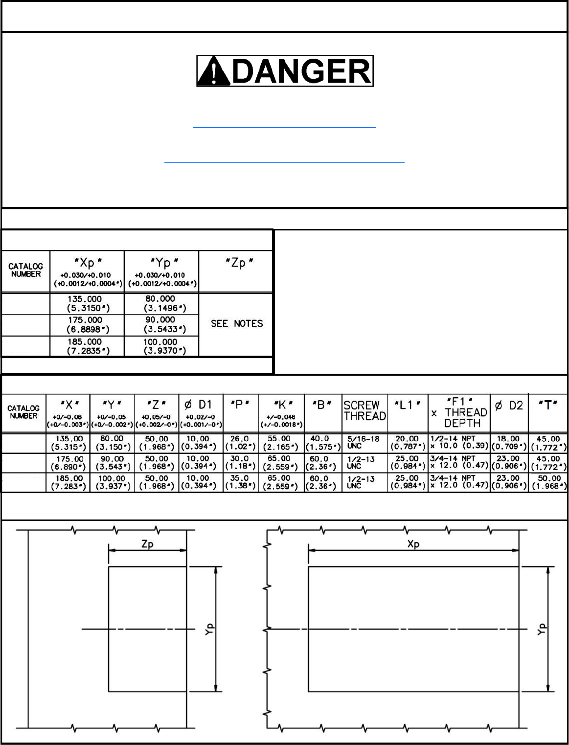
CHILL VENT POCKET DETAIL
INSTALLATION INSTRUCTIONS
Dimensions shown are in millimeters (inches).
Pocket Notes:
•
Perpendicularity and Parallelism of pockets must be
machined such that Chill Vent insert halves mate after
installation without gaps between insert halves.
• Corner radii of Chill Vent insert pockets are to be
machined to suit dimensions shown. Toolmaker is
responsible for modification of corner radii of Chill
Vent Inserts to accommodate machining method used.
• All surfaces of pocket to have a surface finish no
greater than 0.8 μm (micrometers). Check for burrs.
• For Zp, use shim pack to accommodate flushness.
Flushness tolerance must be +0.05/-0 (+0.002/-0”).
POCKET DIMENSIONS
VSCL7US
VLCL7US
VECL7US
65.00
(2.559”)
VSCL7US
VLCL7US
VECL7US
COMPONENT INSERT DIMENSIONS
Example Pocket for one half of Chill Vent
Insert Assembly. Clearance slots for
cooling lines and pipe fittings are not
shown. Key slot, tap counter-bores and
installation for ejector pin not shown.
Toolmaker is responsible to modify
installation to accommodate the
features listed above.