PRO-1250D 100A MID DIN rail three phase four wire energy meter. 1.1 Safety instructions 1.2 Foreword 1.3 MID certificate 1.4 Performance criteria 1.5 Specifications 1.6 Basic errors 1.7 Description 1.8 Dimensions 1.9 Installation 1.10 Operation 1.11 Troubleshooting 1.12 Technical support User manual Version 1.
1.1 Safety instructions Information for Your Own Safety This manual does not contain all of the safety measures for operation of this equipment (module, device) because special operating conditions, local code requirements or local regulations may necessitate further measures. However, it does contain information which must be adhered to for your own personal safety and to avoid damage to the equipment.
Never break the seals to open the front cover as this might influence the functionality or accuracy of the meter, and will void all warranty. Do not drop, or allow physical impact to the meter as there are high precision components inside that may break and render the meter measurement inaccurate. Exclusion of liability We have checked the contents of this publication and every effort has been made to ensure that the descriptions are as accurate as possible.
1.
1.4 Performance criteria: Operating humidity Storage humidity Operating temperature Storage temperature International standard Accuracy class Protection against penetration of dust and water Insulating encased meter protective class 1.
1.7 Description A B C D Front panel Cover Base Security wire slot Material Front panel Cover Base PC inflammable plastic ABS inflammable plastic ABS inflammable plastic A B C D 1.8 Dimensions Height Width Depth Max diameter cable Weight 1.9 130 mm 126 mm 65 mm 11.5 mm 0.7 Kg (net) Installation CAUTION ® 2011 Turn off and if possible lock all sources supplying the energy meter and the equipment that is connected to it before working on it.
WARNING - - - - - ® 2011 Installation should be performed by qualified personnel familiar with applicable codes and regulations. Use isolated tools to install the meter. Fuse or thermal cut-off should be fitted on the supply lines. The meter’s casing is sealed, if not properly looked after, this seal could be broken, voiding the warranty and damaging the meter.
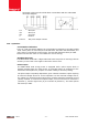
- 1.10 Connection of the wires should be done in accordance with the underneath connection diagram. 1/2 3/4 5/6 7 Ia In/out Ib In/out Ic In/out Neutral 8 and 9 Test pulse output contact Operation Consumption indication There is a red LED which displays the consumption measured by the PRO-1250D 100A. When power is consumed, the LED will flash. The faster the LED flashes, the more power is consumed. For this meter, the LED will flash 400 times per kWh.
1.11 Troubleshooting CAUTION During repair and maintenance, do not touch the meter connecting clamps directly with your bare hands, with metal, blank wire or other conducting material as that will cause an electric shock and possibly cause injury. Turn off and if possible lock all sources supplying the energy meter and the equipment that is connected to it before opening the protection cover and working on it.
Problem Check Solution The power supply indicator (L1, L2 & L3 LED) are off. Is there power connected to the meter? Check the fuses and surge protection. Are L1, L2, L3 and N connected correctly? Make sure the wires are connected properly and tighten the screws if possible. There should be 230V AC between the N and one of the L connections and 400V AC between the L connections when power is supplied to the meter. Maybe there is a fault inside the meter.
1.12 Technical support For questions about one of our products please contact: - The Inepro Metering dealer in your region Your local Inepro Metering distributor Email: support@ineprometering.com www.ineprometering.
® 2011 - 12 - User manual 0025