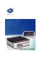
DM&P Group eBox-4300 User’s Manual
COPYRIGHT The information in this manual is subject to change without notice for continuous improvement in the product. All rights are reserved. The manufacturer assumes no responsibility for any inaccuracies that may contain in this document, and makes no commitment to update or to keep current information contain in this manual.
TRADEMARKS ACKNOWLEDGMENT eBox-4300 is the registered trademarks of DMP Electronics Inc. Microsoft®, Windows® and AMI are registered trademarks of Microsoft Corporation and American Megatrends, Inc. in the United States and/or other countries respectively. Other brand names, product names or trade names appearing in this document are the properties and registered trademarks of their respective owners. All names mentioned herewith are served for identification purpose only.
SAFETY INFORMATION WARNING Do not expose your VESA PC to rain or moisture, in order to prevent shock and fire hazard. Never install your VESA PC in wet locations. Do not open the cabinet to avoid electrical shock. Refer to your nearest dealer for qualified personnel servicing. Never touch un-insulated terminals or wire unless your power adaptor and display monitor are disconnected.
REGULATORY FCC CLASS A NOTE This equipment has been tested and found to comply with the limits for a Class A digital device, pursuant to Part 15 of the FCC Rules. These limits are designed to provide reasonable protection against harmful interference when the equipment is operated in a commercial environment.
PURCHASE AGREEMENT PURPOSE: In accordance to the general commercial conduct of Trust and Fair Trade, herewith below is the agreement for the protection for both parties, DMP and Users in pursuant of trading. PRODUCT DESCRIPTION: With this product, herewith also known as eBox-4300, which is a simplified & an economical design of an embedded VESA PC for Special Purpose Personal Computing.
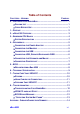
Table of Contents CHAPTERS – HEADING PAGE NO. 0 – UNPACKING YOUR EMBEDBOX........................................................ 1 ` PACKING LIST ............................................................................. 1 ` CHECK BEFORE USE ................................................................... 1 1 – PREFACE ...................................................................................... 2 2 – eBOX-4300 OVERVIEW ..................................................................
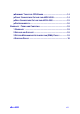
` SUMMARY TABLE FOR CPU BOARD ............................................ 14 ` FRONT CONNECTORS OUTLINE FOR eBOX-4300......................... 14 ` REAR CONNECTORS OUTLINE FOR eBOX-4300 .......................... 15 ` PIN ASSIGNMENTS ..................................................................... 16 WARRANTY : TERMS AND CONDITION ................................................... 18 1 WARRANTY .............................................................................. 18 2 SERVICE AND SUPPORT ...
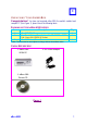
0 UNPACKING YOUR EMBEDBOX Congratulation! You have just acquired eBox-4300, the world’s smallest and compact PC (See Figure 1), please check the following items: PACKING LIST FOR eBOX-4300 SERIES Item c d Description eBox-4300 VEA PC Max. 15-watts External Power Adaptor, Vin: 100~240VAC • 60/50Hz, 1.0A / Vout: +5.0~5.25VDC @ 3A max. eBox-4300 Drivers CD e Q’ty 1 1 1 * Note: The accessories are subject to change without immediate notice.
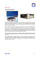
1 PREFACE eBox-4300: VESA PC eBox-4300 is a revolutionary device, that is especially designed for limited physical space and temperature concerns. No matter you are in a jammed office, a crowded place, or public transportation, it can be easily integrated with a VESA LCD to bring you VESA PC access at any time. It can attach to any VESA mounting fixture, allowing it to be securely mounted onto desks, walls, or buildings, and thereby optimizes your work area.
2 eBOX-4300 OVERVIEW Front Panel Power LED The power LED lights up, when system is turn on. HDD LED The HDD LED flashes when the system is working. Please do not turn off the system when HDD start running Power Switch Depress switch to turn on & turn off the systems. CF Slot For connection to Device with CF Card and Micro Driver. Audio Line Out Audio Mic InPower Switch USB port For connection to devices with USB interface (HDD, CD/DVD-ROM, Memory Stick, etc.
3 About Embedded CPU Board System Specification Keyboard and Mouse CPU PS/2 Keyboard and Mouse VIA Eden ULV 500MHz On-Board IDE Main Memory Enhanced 512MB DDR2 header x 1 BIOS Peripheral AMI BIOS 1. USB V2.0 Ports x 3 VGA 2. Serial port x2(This function is only Integrated VIA UniChrome Pro II, 2D/3D Graphics IDE interface, 44-pin box with MPEG4 and WMV9 decoding accelerator. Resolution up to 1,920x1,440 Audio AC97 CODEC, Fully Compliant with AC97v2.
4 PERIPHERALS CONNECTING THE POWER ADAPTOR Power Adaptor To use your VESA PC immediately, take and use the supplied AC adapter as a power source. See the left diagram for visual connection. Connect the DC power jack of the power adaptor to the DC Input jack of eBox4300. Turning ON Your VESA PC Press the power button as indicated on the figure on your left-side, the system will start automatically.
PERIPHERALS CONNECTING THE USB eBox-4300 provides USB port (Two in front & one at the back). Front cabinet USB Ports The second USB port is available for connection to USB devices. Speaker/Earphone eBox-4300 supports Input/Output device for speaker and Microphone CONNECTING SPEAKER/EARPHONE AND WEB Connecting to WEB There is an available RJ-45 LAN jack for connection to the hub of your intranet; and via your server for internet service (see diagram for RJ-45 LAN jack).
CONNECTING THE KEYBOARD AND MOUSE PS/2 Keyboard or Mouse (6-pin) The PS/2 Port is available for connect Keyboard or Mouse.
5 BIOS RECONFIGURING eBox-4300 1. 2. 3. 4. Take note that AMI BIOS is used in the eBox-4300 VESA PC. To reconfigure the VESA PC, depress or hit the key to enter your BIOS setup main menu. Select from the menu, the desired setup for change. Press to go back to main menu. Move your cursor to “Save Settings and Exit”, press “Y” to save the changes that you just made. eBox-4300 will restart accordingly to your new setup.
6 TECHNICAL SPECIFICATION Features Description CPU VIA Eden ULV 500MHz BIOS AMI BIOS System Memory Onboard 512MB DDR2 Expansion 1x Mini-PCI connector (option for eBox-4300-M and eBox-4300-JSK) I/O MIO USB 1 x EIDE (44-pin) 2 x RS-232**, 1x PS/2 for K/B or Mouse 1 x RJ-45 Ethernet Connector 1 x Type I/II Compact Flash slot 3 x USB 2.0 Ports (two in front) Display Display Memory Up to 128MB Share System Memory Resolution Up to 1920 x 1440 Audio AC97 2.1 (Codec) AC97 V2.
7 TAKING CARE YOUR VESA PC This section gives you guidelines on using eBox-4300 VESA PC – Safe using, Storing and Handling.
USING CABLES FOR CONNECTION To avoid problem, use only the specified interface cables in your accessory bag. The supplier will not be responsible for the connection arising from the other unspecified peripheral equipment. Do not use cut or damaged cables for connection. CLEANING YOUR VESA PC Clean the VESA PC with a soft, dry cloth or a soft cloth lightly moistened with a mild detergent solution.
8 TROUBLESHOOTING This section describes the techniques of resolving some basic problems that you encounter when using your VESA PC. For more troubleshooting guidelines, please contact your nearest dealer for technical support. TROUBLESHOOTING YOUR VESA PC A. VESA PC does not start Make sure the VESA PC is properly secured and plugged into a power source before it is turned on. Make sure the power indicator shows the power is on. See section 2 for more information about “eBox-4300 Overview”.
C. “Operating System Not Found” – A message indicating that “Operating system not found” appear when my VESA PC starts (Windows won’t start) Enter your BIOS setup main menu by pressing key, be sure that your C: drive is enable. If Windows still does not start, follow these steps to initialize the BIOS: 1. Turn off the VESA PC. 2. Remove any peripheral devices connected to the VESA PC. 3. Restart the VESA PC.. 4. Press to enter BIOS Setup main menu window. 5.
APPENDIX ONBOARD CONNECTORS SUMMARY SUMMARY TABLE FOR CPU BOARD Nbr Description Type of Connections SW1 Power Button Power Button J1 VGA Connector D-Sub Connector 8-pin J4 USB (Back) USB Connector 8-pin J5, J6 USB (Front) USB Connector 8-pin J7 PS/2 keyboard or Mouse Mini DIN Connector 6-pin J8 Line Out Audio Jack J9 Mic In Audio Jack J10 IDE connector Box Header 22x2 2.0mm 44-pin COM Port Box Header 5x2 2.0mm 10-pin J11,J12: Pin nbrs.
` REAR CONNECTORS OUTLINE FOR eBOX-4300 DC Power Jack Power Switch eBox-4300 PS/2 KB/MS VGA RJ-45 LAN Serial Ports (Optional) USB Wireless ANT (Optional) 15
` PIN ASSIGNMENTS Power SW – Push Button Switch J4:PS/2 Keyboard or Mouse – 6-pin Mini-Din Connector Pin # 1 2 3 4 5 6 Signal Name KBCLK PMCLK GND KBDAT PMDAT SB5V Pin # Status | ON O OFF J14: DC-IN (5V) – 3-pin Mini-Din Lock Pin Socket Pin # Signal Name 1 VCC 2 GND 3 NC J3: USB (90o)– 4-pin USB Type 1 Connector (Vertical Type) Pin # 1 2 3 4 5 6 Signal Name VCC USB0USB0+ GND GGND GGND J8: RJ-45 Connector eBox-4300 Pin # Signal Name Pin # Signal Name 1 FTXD+ 2 FTXD- 3 FRXIN+ 4
` PIN ASSIGNMENTS J1: VGA – 15-pin D-Sub Connector Pin # 1 2 3 4 5 Signal Name MR MG MB NC GND Pin # Signal Name 6 GND 7 GND 8 GND 9 NC 10 GND 1 2 3 4 5 Signal Name GND MIC1 Open Touch Open Touch VREFOUT Pin # 1 2 3 4 5 6 1 2 3 4 5 Signal Name VCC USB2USB2+ GND NC NC Power BTN – Push button Action J9: Line-out – 5-pin Phone Jack Pin # Signal Name NC VCC HYSYNC VSYNC VCC J5:USB (USB2): For connection to external USB device –4-pin USB Type 1 Connector (H) J10: MIC_IN – 5-pin RCA Phone Jack Pin #
WARRANTY TERMS AND CONDITIONS 1. Warranty The warranty terms for eBox-4300 are twelve (12) months from the beginning on the date of invoice. During the warranty period, DMP Electronics Will repair replace the product covered under this limited warranty. 2. Service and Support DMP Electronics Inc. provides the technical support for hardware problems with your system throughout the warranty period.
MEMO eBox-4300 19