
User manual


Page 7
Installation
2841 E. Industrial Drive Springfield, MO 65802-6310 800-641-4282
XR10/XR20 Installation Guide
Bell Output
7.1 Terminals 5 and 6
Nominal 12 VDC is supplied by terminal 5 on the panel to power alarm bells or horns. The output is rated for a
maximum output of 1.5 Amps. This output can be steady or pulsed depending upon the Bell Action specified in
Output Options. Terminal 6 is the ground reference for the bell circuit.
Keypad Data Bus
8.1 Description
Terminals 7, 8, 9, and 10 of the XR10/XR20 panel are designated as the keypad data bus. In addition to
keypads, the XR20 allows the connection of any combination of zone expanders, 5845LX Glassbreak Detectors,
6155LX PIRs, and DS775LX PIRs to the data bus up to the maximum of four devices.
8.2 Terminal 7 - RED
Nominal 12 VDC is supplied at terminal 7 to power Security Command keypads and zone expanders. This is
also where power for any auxiliary device is supplied. The ground reference for terminal 7 is terminal 10. The
maximum output is rated at 500mA. All auxiliary devices totalled together must not exceed the panel's maximum
current rating of 500mA.
8.3 Terminal 8 - YELLOW
Data receive from keypads and zone expanders.
8.4 Terminal 9 - GREEN
Data transmit to keypads and zone expanders.
8.5 Terminal 10 - BLACK
Terminal 10 is the ground reference for Security Command keypads, zone expanders, and any auxiliary devices
being powered by terminals 7 and 11.
Smoke and Glassbreak Detector Output
9.1 Terminal 11
Nominal 12 VDC at 100mA maximum (shared by terminal 25) is supplied at terminal 11 to power 4-wire smoke
detectors or other auxiliary powered devices. This output can be turned off by the user for 5 seconds using the
Sensor Reset Menu Option. Terminal 10 is the ground reference for terminal 11.
Burglary Zones
10.1 Description
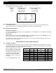
Terminals 12 to 24 are the nine burglary zones. For programming purposes, the zone numbers are 1 to 9. The
zone configurations on terminals 12 to 24 are described below.
Terminal Function Terminal Function
12 Zone 1 voltage sensing 19 Ground for zones 5 & 6
13 Ground for zones 1 & 2 20 Zone 6 voltage sensing
14 Zone 2 voltage sensing 21 Zone 7 voltage sensing
15 Zone 3 voltage sensing 22 Ground for zones 7, 8, & 9
16 Ground for zones 3 & 4 23 Zone 8 voltage sensing
17 Zone 4 voltage sensing 24 Zone 9 voltage sensing
18 Zone 5 voltage sensing
The voltage sensing terminal measures the voltage flowing through the 1k Ω End Of Line resistor to the zone's
ground terminal. Dry contact sensing devices can be used in series (normally-closed) or in parallel (normally-
open) with any of the burglary protection zones.