
user manual


P83848 A
Sheet 4 of 7
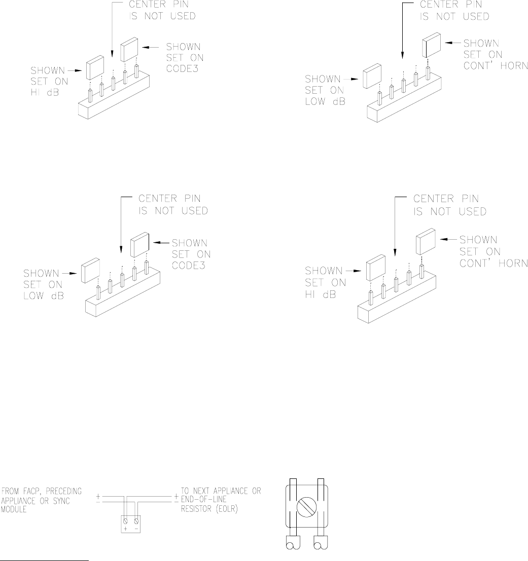
Figure 2: Jumper plug settings for High dB and Code 3. Figure 3: Jumper plug settings for Low dB and Continuous Horn.
Figure 4: Jumper plug settings for Low dB and Code 3. Figure 5: Jumper plug settings for High dB and Continuous Horn.
(Use needle nose pliers to pull and properly set the jumper
plugs.)
No jumper plugs are needed for Continuous Horn and low dB settings.
However, it is recommended that the jumper plug be retained in the unit
for future use (if needed) as shown in Figure 3, 4 and 5.
Note: The Audible Horn Strobe must be set for code 3 when used with the sync module.
WIRING INFORMATION:
Figure 6. Figure 7.
When the sync module is used, the audible tone will be the
code 3 sound only. Refer to Sync Module installation
instruction sheets Sync Module (P83850) and Dual Sync
Module (P83844) for additional information.
1) Audible Horn Strobe Appliances have in-out
wiring terminals that accepts two #12 to 18
American Wire Gauge (AWG) wires at each
screw terminal. Strip leads 3/8” inches for
connection to screw terminals.
2) Break all in-out wire runs on supervised circuit
supervision as shown in Figure 7. The polarity
shown in the wiring diagrams is for the
operation of the appliances. The polarity is
reversed by the FACP during supervision.