
Specifications

690/790 Security Command LCD Keypads
Description
The 690 and 790 Security Command LCD Keypads provide three 2-button Panic keys, an AC power LED, an Armed LED,
32-character display, backlit keyboard with easy-to-read lettering, and a built-in speaker. The 790 additionally provides
four fully programmable Class B protection zones you can program for a variety of burglary and fire applications.
The 690F and 790F Security Command LCD keypads do not provide an Armed LED. These keypads may be installed in
fire only applications.
Installing the Keypad
The keypad housing is made up of two parts: the front, which contains the circuit board
and other components, and the base. To mount the keypad, remove the base from the
front by inserting a flat screwdriver into one of the openings on the bottom. Twist the
screwdriver while pulling the halves apart. Repeat with the other opening.
The 690 and 790 keypads use the same plastic housing and are designed to easily install
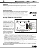
on any 4-square box, 3-gang switch box, 695 and 696 backbox, or flat surface. Figure 1
shows the mounting hole locations on the base of the keypad housing.
Wiring the Keypad using the Wiring Harness
The 690 keypad is supplied with a
4-wire harness for connection to the
panel's keypad bus.
The 790 keypad is supplied with a
12-wire harness. Four wires are for
connection to the keypad bus, just like
the 690 keypad harness. The
remaining eight wires are for the four
zone inputs: two wires for each zone.
The harness wire colors are shown in
Figure 1. Use 1k Ohm EOL resistors
on zones 1 through 4.
Observe the wire colors when
connecting the red, yellow, green, and
black wires to the keypad bus. When
wiring directly to the panel terminals,
connect the red wire the terminal 7,
the yellow to terminal 8, green to 9,
and the black wire the terminal 10.
Wiring Specifications
1. You can install individual keypads on wire runs of up to 500 feet using 22-gauge wire or up to 1,000 feet using
18-gauge wire. To increase the wire length or add additional devices, a power supply is required.
2. Maximum distance for any one keypad bus circuit (length of wire) is 2,500 feet regardless of the gauge of wire.
This distance can be in the form of one long wire run or multiple branches with all wiring totaling no more than
2,500 feet.
3. Maximum number of devices per 2,500 feet circuit is 40. (Note: Each panel allows a specific number of
supervised keypads. Additional keypads can be added in the unsupervised mode. Refer to the panel’s installation
guide for the specific number of supervised keypads that are allowed.)
4. Maximum voltage drop between the panel (or auxiliary power supply) and any device is 2.0 VDC. If the voltage at
any device is less than the required level, an auxiliary power supply should be added at the end of the circuit. The
2.0 VDC drop minimum has not been verified by UL.
Refer to the 710 Module Installation Sheet (LT-0310) for more information. Also see the Trouble-Free LX-Bus/Keypad
Bus Wiring Application Note (LT-2031).
INSTALLATION SHEET
Figure 1: 690/790 Keypad Base with 790 Harness
Black - Ground
Green - Receive Data
Yellow - Send Data
Red - Auxiliary Power
Yellow/White
White/Yellow
- Zone 4
Orange/White
White/Orange
- Zone 3
Red/White
White/Red
- Zone 2
Brown/White
White/Brown
- Zone 1
1K EOL
1K EOL
1K EOL
1K EOL
Surface and Backbox
Mounting Holes
Back of Keypad Base
Combined 4-Square and
3-Gang Switch Box
Mounting Holes
Surface and Backbox
Mounting Holes
Surface and Backbox
Mounting Holes