
Installation guide

Digital Monitoring Products 690/690F/790/790F/693/793 Installation Guide
10
690/690F/790/790F/693/793 Installation Guide Digital Monitoring Products
11
Keypad Door Strike
Area and All/Perimeter Door Strike
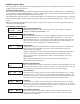
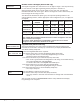
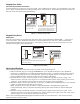
From the Status List, present your card to the reader. Once validated by the system, all areas assigned to your code
arm or disarm automatically and the 793 keypad Door Strike relay activates. Home/Away systems only activate the
793 Door Strike relay when arming and disarming.
ABC SECURITY
MON 10:20 AM
While the keypad is in
the Status List, present
your access card
.
The relay activates for 5 seconds during
which time you can open the door
.
Once you open the door, you have 40
seconds to exit and close the door
befo
re the Zone 2 Soft-Shunt expires.
Figure 11: Present Access Card
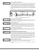
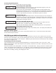
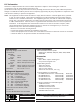
Keypad Entry Delay
All Systems
Once the protected door is opened and the entry delay starts, the keypad displays ENTER CODE: - . Present your
card to the reader. Once validated by the system, all areas assigned to your code arm or disarm automatically
and the 793 keypad Door Strike relay activates. Area systems provide a delay to allow selected areas only to be
disarmed. See Keypad Arming and Disarming.
ABC SECURITY
ENTER CODE:>
Access door opens.
The System disarms the area and activates the 793
Door Strike Relay.
Figure 12: Entry Delay
Wiring Specications
When planning a keypad bus installation, keep in mind the following specications:
1. DMP recommends using 18 or 22-gauge unshielded wire for all keypad and LX-Bus circuits. Do Not use
twisted pair or shielded wire for LX-Bus and keypad bus data circuits. To maintain auxiliary power integrity
when using 22-gauge wire do not exceed 500 feet. When using 18-gauge wire do not exceed 1,000 feet.
Install an additional power supply to increase the wire length or add devices.
2. Maximum distance for any one circuit (length of wire) is 2,500 feet regardless of the wire gauge. This
distance can be in the form of one long wire run or multiple branches with all wiring totaling no more than
2,500 feet. As wire distance from the panel increases, DC voltage on the wire decreases.
3. Maximum number of devices per 2,500 feet circuit is 40. On XR500 Series and XR2500F panels, the maximum
number of LX-Bus devices per 2,500 foot circuit is 25.
Note: Each panel allows a specic number of supervised keypads. Add additional keypads in the
unsupervised mode. Refer to the panel installation guide for the specic number of supervised keypads
allowed.
4. Maximum voltage drop between the panel (or auxiliary power supply) and any device is 2.0 VDC. If the
voltage at any device is less than the required level, add an auxiliary power supply at the end of the circuit.
When voltage is too low, the devices cannot operate properly.
Refer to the LX-Bus/Keypad Bus Wiring Application Note (LT-2031) for more information. Also see the 710/710F
Module Installation Sheet (LT-0310).