
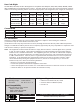
Specifications

INSTALLATION SHEET
690/690F, 790/790F Security Command
®
Keypads
791/793 Easy Entry™ Keypads
Description
The DMP 690/690F, 790/790F Security Command® LCD Keypads and 791/793 Easy Entry™ LCD Keypad are the
industry’s rst burglary/re keypads with integrated access control capability. Each keypad provides four 2-button
Panic keys, an AC power LED, an Armed LED, 32-character display, backlit keyboard with easy-to-read lettering and
an internal speaker. The 790/790F and 791/793 keypads provide four fully programmable Class B, Style A protection
zones you can program for a variety of burglary, re, and access control applications. The 793 keypads also provide
a built-in card reader.
Note: The 690F and 790F Security Command LCD keypads do not provide an Armed LED. These keypads may be
installed in re only applications.
Installing the Keypad
The keypads each use the same plastic housing. They are all designed to easily install on any 4” square box, 3-gang
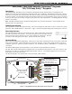
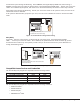
switch box, 695 and 696 backbox, or at surface. Figure 1 shows the keypad housing base mounting hole locations.
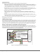
Removing the Base
The keypad housing is made up of two parts: the front, which contains the circuit board
and other components, and the base. To mount the keypad, remove the base from the
front by inserting a at screwdriver into one of the openings on the bottom. Twist the
screwdriver while pulling the halves apart. Repeat with the other opening.
Harness Wiring
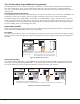
Figure 1 shows wiring harness assignments. Observe wire colors when connecting the red, yellow, green, and black
wires to the keypad bus. When wiring directly to the panel terminals, connect red to panel terminal 7, yellow to
terminal 8, green to 9, and black to panel terminal 10. Use 1k Ohm EOL resistors, DMP Model 311, on keypad zones
1 through 4.
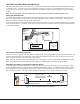
The 690 and 690F keypads are supplied with a 4-wire harness for panel keypad bus connection.
The 790, 790F, and 791/793 keypads are supplied with a 12-wire data bus/zone harness. Four wires connect to the
keypad bus, the same way the 690 and 690F keypad harness connects. The remaining eight wires are for the four
zone inputs: two wires for each zone.
The 791/793 keypad is also supplied with one 5-wire output/reader harness.
Surface and Backbox
Mounting Holes
Combined 4-square
and 3-gang switch box
Mounting Holes
Keypad Back
Surface and Backbox
Mounting Holes
1K EOL
1K EOL
1K EOL
1K EOL
Green/White – Connect Reader Data 0
Whit
e – Connect Reader Data 1
Orange – Door Strike Normally Open
Gray – Door Strike Common
Violet
– Door Strike Normally Closed
Yellow/Whit
e
White/Yello
w
Orange White
White/Orange
Red/White
White/Red
Brown/White
White/Brow
n
Black – Ground
Green – Receive Data
Yellow – Send Data
Red – Keypad Power
– Zone
4
– Zone 3
– Zone
2
– Zone 1
Output Reader
791/793 Keypads
Zones 1 through 4
790/790F, 791 and
793 Keypads
All Keypads
Figure 1: Keypad Back Showing Wiring Harness Assignments