User Guide Dobot M1 User Guide Issue: V1.0.4 Date: 2018-08-30 Shenzhen Yuejiang Technology Co.
Dobot M1 User Guide Copyright © ShenZhen Yuejiang Technology Co., Ltd 2018. All rights reserved. No part of this document may be reproduced or transmitted in any form or by any means without prior written consent of Yuejiang Technology Co., Ltd Disclaimer To the maximum extent permitted by applicable law, the products described (including its hardware, software and firmware, etc.) in this document are provided AS IS, which may have flaws, errors or faults.
Dobot M1 User Guide Preface Preface Purpose This Document describes the functions, technical specifications, installation guide and system commissioning of Dobot M1, making it easy for users to fully understand and use it. Intended Audience This document is intended for: Customer Engineer Sales Engineer Installation and Commissioning Engineer Technical Support Engineer Change History Date Change Description 2018/06/30 Add certification specification Delete 3.
Dobot M1 User Guide 2.3.1 Workspace 2.4 Technical Specifications 5.4.1 Connecting Serial Port 6.1.2 Alarms Description 6.2 Operating Teaching and Playback 6.8 Operating Web Management Preface Symbol Conventions The symbols that may be founded in this document are defined as follows.
Dobot M1 User Guide Contents Contents Security Precautions ................................................................................................ 1 1.1 General Security................................................................................................................ 1 Service Security ................................................................................................................ 2 Introduction .......................................................................
Dobot M1 User Guide Contents Debugging Dobot M1 ........................................................................................ 40 Debugging the Power of Dobot M1 .................................................................. 42 Setting IP Address ............................................................................................. 42 Debugging Emergency Stop Function ............................................................... 45 Debugging Motion Function .........................
1 Security Precautions Dobot M1 User Guide Security Precautions This topic describes the security precautions that should be noticed when using this product. Please read this document carefully before using the robotic arm for the first time. This product need to be carried out in an environment meeting design specifications, you cannot remold the product without authorization, otherwise it could lead to product failure, and even personal injury, electric shock, fire, etc.
Dobot M1 User Guide 1 Security Precautions People cannot repair and disassemble the robotic arm without professional training. If there is a problem with the robotic arm, please contact Dobot technical support engineer in time. Before operating and maintaining the robotic arm, the personnel responsible for the installation, operation and maintenance must be trained to understand the various security precautions and to master the correct methods of operation and maintenance.
Dobot M1 User Guide 1 Security Precautions phenomenon. At that point, you need to click J3+ under Joint coordinate system on the M1Studio page to jog robotic arm to the position where the J3 value is above 10mm, and then the alarm will be cleared. When powering on for the first time, please ensure that the emergency stop switch has been opened (The emergency stop button is bumped). Otherwise, the robotic arm will not work normally.
2 Introduction Dobot M1 User Guide Introduction Overview Dobot Master 1st generation robotic arm (Dobot M1 for short) focuses on the light industrial market with great potential, and supports teaching, playback, script control, blockly graphic programming, laser engraving, 3D printing, vision identity and other functions, which is flexibly used in intelligent sorting, circuit board soldering and other automatic production lines, so that it can become the sword to solve practical problems for light industr
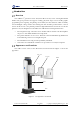
2 Introduction Dobot M1 User Guide Working Principle This topic describes the workspace, principle, size, and technical specifications of Dobot M1. Workspace Figure 2.2 shows the workspace. Figure 2.2 Workspace of Dobot M1 Coordinate System Dobot M1 has two types of coordinate system, the joint one and the Cartesian one, as shown in Figure 2.3 and Figure 2.4 respectively. NOTE The data shown in Figure 2.3 indicates the mechanical limitation. Issue V1.0.
2 Introduction Dobot M1 User Guide Figure 2.3 Joint coordinate system Figure 2.4 Issue V1.0.4 (2018-08-30) Cartesian coordinate system User Guide 6 Copyright © Yuejiang Technology Co.
2 Introduction Dobot M1 User Guide Joint coordinate system: The coordinates are determined by the motion joints. Dobot M1 contains four joints. J1, J2, and J4 are the rotating joints, which are located and oriented in the horizontal plane. And their axes are parallel to each other. The positive direction of these joints is counter-clockwise. J3 is the moving joint, which is used for the movement of the end effector in the perpendicular plane. The positive direction of J3 is vertical upward.
2 Introduction Dobot M1 User Guide Figure 2.6 Lefty hand orientation Motion Function The motion modes of Dobot M1 include Jogging, Point to Point (PTP), ARC, and CIRCLE. 2.3.4.1 Jogging Mode Jogging mode is the mode jogging Dobot M1 along the Cartesian coordinate system or Joint coordinate system when teaching. NOTE This topic describes jogging mode by the GUI operation of M1Studio.
2 Introduction Dobot M1 User Guide direction. 2.3.4.2 Point to Point Mode (PTP) PTP mode supports MOVJ, MOVL, and JUMP, which means point to point movement. The trajectory of playback depends on the motion mode. MOVJ: Joint movement. From point A to point B, each joint will run from initial angle to its target angle, regardless of the trajectory, as shown in Figure 2.7. Figure 2.7 MOVL/MOVJ mode MOVL: Rectilinear movement.
2 Introduction Dobot M1 User Guide In JUMP mode, if the starting point or the end point is higher than or equal to Limit, or the height that the end effector lifts upwards is higher than or equal to Limit, the trajectory is different to that of Figure 2.8. Assuming that point A is the starting point, point B is the end point, Limit is the maximum lifting height, and Height is the lifting height. Point A and point B are both higher than Limit, but point A is higher than point B.
2 Introduction Dobot M1 User Guide Limit A The height of point A and point B are both the same as Limit. A B Limit Point A and point B are both lower than Limit, but the height that the height of point A plus Height and that of point B plus Height is higher than Limit. Limit B A 2.3.4.3 ARC Mode (ARC) The trajectory of ARC mode is an arc, which is determined by three points (the current point, any point and the end point on the arc), as shown in Figure 2.9.
2 Introduction Dobot M1 User Guide Figure 2.9 ARC mode 2.3.4.4 CIRCLE Mode (CIRCLE) The CIRCLE mode is similar to ARC mode, of which the trajectory is a circle. In CIRCLE mode, it is necessary to confirm the three points with other motion modes. 2.3.4.5 Application Scenarios The application scenario depends on the trajectory in motion mode, as shown in Table 2.1. Table 2.
2 Introduction Dobot M1 User Guide magnitude Rear arm -90°- 90° -85°- 85° Forearm -135°- 135° -135°- 135° Z-axis screw 0mm- 250mm 10mm- 235mm End-effector -360°- 360° -360°- 60° rotation Maximum speed Joint speed of 180°/s Forearm and Rear Arm Resultant 2000mm/s speed of the Forearm and Rear Arm Speed of Z- 1000mm/s axis Repeatability 0.
2 Introduction Dobot M1 User Guide Figure 2.10 Issue V1.0.4 (2018-08-30) Size of Dobot M1 User Guide 14 Copyright © Yuejiang Technology Co.
3 Hardware Installation Dobot M1 User Guide Hardware Installation Environment Requirements The operating temperature of Dobot M1 ranges from 5 °C to 40 °C. The operating humidity ranges from 45% to 75% (non-condensing). Installing the Base of Dobot M1 The stability of Dobot M1 depends on the installation of the base of Dobot M1. You can design the platform according to the size of the hole of the base and the real environment for fixing Dobot M1.
3 Hardware Installation Dobot M1 User Guide (Optional) Installing End Effector You can install the matching gripper, suction cup, or laser on the end effector of Dobot M1 for transporting, intelligent sorting and laser engraving. Figure 3.2 shows the size of the end effector of Dobot M1. Figure 3.2 Size of the terminal Installing Laser Engraving Kit Figure 3.3 shows the laser kit. Issue V1.0.4 (2018-08-30) User Guide 16 Copyright © Yuejiang Technology Co.
3 Hardware Installation Dobot M1 User Guide Figure 3.3 Laser kit Procedure Figure 3.4 connect to Forearm I/O interface Issue V1.0.4 (2018-08-30) User Guide 17 Copyright © Yuejiang Technology Co.
3 Hardware Installation Dobot M1 User Guide Installing 3D Printing Kit Figure 3.5 shows the 3D printing kit. Figure 3.5 3D printing kit Procedure Figure 3.6 Issue V1.0.4 (2018-08-30) Connect to Forearm I/O interface User Guide 18 Copyright © Yuejiang Technology Co.
3 Hardware Installation Dobot M1 User Guide Press down the lever on the extruder by hand, and push down the filament to the bottom via pulley, as shown in Figure 3.7 and Figure 3.8. Figure 3.7 Push down the filament (1) Figure 3.8 Push down the filament (2) (Optional) Installing Air Pump It is necessary to install the matching air pump when using the gripper or suction cup for grabbing objects. The air pump is controlled over the I/O interface. For details, please see 6.7 Operating I/O Assistant.
3 Hardware Installation Dobot M1 User Guide Figure 3.9 shows the air pump. Table 3.1 lists the description of the cables that are shown in the yellow box of this figure. Figure 3.9 Table 3.1 Air pump Cable Description Color Description Red VCC_24V Black PGND Yellow OUT1: Control the intake and outtake of the air pump Blue OUT2: Control the status of the air pump If the air pump is connected to the base I/O interface.
3 Hardware Installation Dobot M1 User Guide Figure 3.10 Air pump connection NOTICE When air pump is connected to I/O interface, the terminals of air pump cannot be exposed to the air, to avoid short circuit. For matching all I/O interfaces, terminals of air pump will be slightly longer. If that happens, you need to cut them to an appropriate length. Figure 3.11 and Figure 3.12 show the standard and non-standard connection of the terminals respectively. Figure 3.11 Issue V1.0.
3 Hardware Installation Dobot M1 User Guide Figure 3.12 Issue V1.0.4 (2018-08-30) Non-standard connection User Guide 22 Copyright © Yuejiang Technology Co.
4 Electrical Specifications Dobot M1 User Guide Electrical Specifications The address of the I/O interfaces of Dobot M1 are unified. Interface Board The interface board of Dobot M1 is located on the back of the base, as shown in Figure 4.1. Table 4.1 shows the function description. ② ① ③ ④ ⑦ ⑪ ⑩ ⑥ ⑤ ⑨ ⑧ Figure 4.1 Interface board of Dobot M1 Table 4.1 Description of the interface borad No.
4 Electrical Specifications Dobot M1 User Guide Table 4.2 lists the status of the LED indicators on the interface board and the external power box Table 4.2 Description of the LED indicators Item Description External power box The LED indicator is steady on when the external power box is powered on.
4 Electrical Specifications Dobot M1 User Guide Figure 4.2 Table 4.3 Power adapter The power adapter input interface description No. Name Function Voltage/Current 1 AC_L L of the AC power 100V-240V AC/2.6A 2 AC_N N of the AC power 100V-240V AC/2.6A 3 GND GND GND 4.3.1.2 DC output Interface Table 4.4 The power adapter output interface description No.
4 Electrical Specifications Dobot M1 User Guide 4.3.2.1 Power Interface Table 4.5 Description of the power interface PIN Name Function Voltage/Current 1 VIN Positive electrode of the DC 48V DC/5A power 2 GND Negative electrode of the DC GND/5A power Issue V1.0.4 (2018-08-30) User Guide 26 Copyright © Yuejiang Technology Co.
4 Electrical Specifications Dobot M1 User Guide 4.3.2.2 Base I/O Interface Table 4.
4 Electrical Specifications Dobot M1 User Guide 4.3.2.3 CAN Bus Interface Table 4.7 The CAN bus interface description PIN Name Function Voltage/Current 1 VBUS Positive of VBUS 48V/5A 2 GND Negative of VBUS GND/5A 3 CAN1_H CAN bus CAN level 4 CAN1_L CAN bus CAN level 4.3.2.4 Forearm I/O Interface Table 4.
4 Electrical Specifications Dobot M1 User Guide Table 4.
4 Electrical Specifications Dobot M1 User Guide PIN Name Function Voltage/Current 25 DOUT1 Digital output 0V,24V/2mA 26 DIN2 Digital input 0V,24V/<100mA 27 DOUT4 Digital output 0V,24V/2mA 28 DOUT3 Digital output 0V,24V/2mA 29 CAN2_L CAN bus CAN level 30 DOUT5 Digital output 0V,24V/2mA 31 DOUT7 Digital output 0V,24V/2mA 32 DIN8 Digital input 0V,24V/<100mA 33 AIN4 Analog input 0V~10V/<100mA 34 FPGA_DOUT2 Digital output 0V,24V/2mA Digital output 0V,24V/2mA Digita
4 Electrical Specifications Dobot M1 User Guide PIN Name Function Voltage/Current 49 AOUT1 Analog output, reserved 0V-10V/10mA 50 DOUT6 Digital output 0V,24V/2mA 51 DOUT8 Digital output 0V,24V/2mA 52 AIN1 Analog input 0V-10V/<100mA 53 DOUT10 Digital output 0V,24V/2mA 54 DOUT9 Digital output 0V,24V/2mA 55 FPGA_DOUT1 Digital output 0V,24V/2mA (DOUT11) 56 GND Negative of the analog power GND/1A 57 PGND Negative of the logic power GND/5A 58 PGND Negative of the logic
Dobot M1 User Guide 5 Installation and Commissioning Installation and Commissioning Installing Software The main software for Dobot M1 is M1Studio. You can use playback, script control, 3D printing, etc. Environment Requirements The supported OSs are as follows. Win7 Win8 Win10 Obtaining M1Studio Software Package Before operating Dobot M1, please download the correct version of M1Studio. The path is www.dobot.cc/downloadcenter/dobot-m1.html#most-download.
5 Installation and Commissioning Dobot M1 User Guide Figure 5.1 The M1Studio installation GUI After 40 seconds later, the DriverSetup(X64) page is displayed. The Driver install success! dialog box is displayed, which indicates that the installation of M1Studio driver is successful. Verifying Installation Please double-click M1Studio after installation. If M1Studio can be started, the installation is successful.
5 Installation and Commissioning Dobot M1 User Guide Figure 5.2 The VC++ libraries Connecting Power Supply Figure 5.3 shows the power supply cables and power adapter. No.1 in Figure 5.3 indicates power supply output cable, No.2 indicates power supply input cable, and No.3 indicates power adapter. Figure 5.3 Issue V1.0.4 (2018-08-30) Power cables and power adapter User Guide 34 Copyright © Yuejiang Technology Co.
5 Installation and Commissioning Dobot M1 User Guide The input and output interfaces of the power adapter are shown in Table 5.1 and Table 5.2.ss Table 5.1 The power adapter input interface description No. Name Function Voltage/Current 1 AC_L L of the AC power 100V-240V AC/2.6A 2 AC_N N of the AC power 100V-240V AC/2.6A 3 GND GND GND Table 5.2 The power adapter output interface description No.
Dobot M1 User Guide Figure 5.4 5 Installation and Commissioning Connect power supply input cable to power adapter NOTICE If the type of the power input supply is America-standard, please connect the G pin on the power input supply to the Ground pin on the power adapter, the W pin to the N pin, and the Z pin to the L pin. Issue V1.0.4 (2018-08-30) User Guide 36 Copyright © Yuejiang Technology Co.
5 Installation and Commissioning Dobot M1 User Guide Figure 5.5 Connect power supply output cable to power adapter Figure 5.6 Issue V1.0.4 (2018-08-30) Connect to Dobot M1 User Guide 37 Copyright © Yuejiang Technology Co.
Dobot M1 User Guide 5 Installation and Commissioning Connecting Emergency Stop Switch Before operating Dobot M1, please connect it to the emergency stop switch to ensure that Dobot M1 can be stopped immediately during running. When powering on for the first time, please ensure that the emergency stop switch has been opened (The emergency stop button is bumped). Otherwise, the robotic arm will not work normally. If the emergency stop switch is not opened, please rotate the emergency stop button clockwise.
5 Installation and Commissioning Dobot M1 User Guide Connecting External Cables Connecting Serial Port Prerequisites Please prepare USB to serial line. One end is standard USB port, the other end is 9-pins serial port. Procedure Figure 5.9 The serial port connection After startup, you can check the corresponding serial information from the serial drop-down list on the upper left pane of the M1Studio page. Figure 5.
Dobot M1 User Guide 5 Installation and Commissioning You have connected the PC to a router. Procedure NOTICE This topic describes how to connect a PC to Dobot M1 using a router. It is applicable to the scenario in which robotic arms are connected to the same PC. If only one robotic arm is connected to the PC, you can connect robotic arm to the PC directly using the network cable without router.
5 Installation and Commissioning Dobot M1 User Guide the value is below 10mm, an alarm about limitation is generated and meanwhile the red indicator on the base of robotic arm is on, which is a normal phenomenon. At that point, you need to click J3+ under Joint coordinate system to jog robotic arm to the position where the J3 value is above 10mm, and then the alarm will be cleared. If Connect turns to Disconnect, the connection is successful, and Dobot M1 can be controlled by M1Studio. Figure 5.
5 Installation and Commissioning Dobot M1 User Guide Debugging the Power of Dobot M1 Prerequisites You have powered on Dobot M1. You have connected Dobot M1 and an emergency stop switch. Procedure Hold down the power button in the base of Dobot M1 for about 5 seconds, and then release your fingers. If all LED indicators are off and Dobot M1 moves down automatically, Dobot M1 is powered off successfully.
5 Installation and Commissioning Dobot M1 User Guide Figure 5.13 IP address of Dobot M1 5.5.3.2 Changing the IP Address of Dobot M1 NOTICE If you connect Dobot M1 to a PC over a network cable directly, you need to set IP address and subnet mask of Dobot M1. The IP address of Dobot M1and the PC must be on the same network segment without conflict. The subnet masks of them must be the same.
5 Installation and Commissioning Dobot M1 User Guide If Disconnect turns to Connect, Dobot M1 is disconnected from the PC. If Connect turns to Disconnect, the connection by the network cable is successful. 5.5.3.3 (Optional) Changing the IP Address of the PC You can change the IP address of the PC to make it on the same network segment as that of Dobot M1. NOTE This section uses Win7 OS as an example to describe how to change the IP address. Please change it based on site requirements.
5 Installation and Commissioning Dobot M1 User Guide Figure 5.14 IP address modification If Disconnect turns to Connect, Dobot M1 is disconnected from the PC. If Connect turns to Disconnect, the connection by the network cable is successful. Debugging Emergency Stop Function Prerequisites Dobot M1 has been powered on. Dobot M1 has been connected to a PC successfully. Dobot M1 has been connected to an emergency stop switch. Procedure Issue V1.0.
5 Installation and Commissioning Dobot M1 User Guide Figure 5.15 Emergency stop Dobot M1 is stopped immediately with an alarm about emergency stop and the red LED indicator on the base is on, which indicates that the emergency stop function is OK. The emergency stop button is bumped when rotating to 45°, which indicates the stopped status is cleared. Figure 5.16 Alarm tip Issue V1.0.4 (2018-08-30) User Guide 46 Copyright © Yuejiang Technology Co.
Dobot M1 User Guide Figure 5.17 5 Installation and Commissioning Alarm tab Debugging Motion Function For details about motion functions supported by Dobot M1, please see 2.3.4 Motion Function. 5.5.5.1 Debugging Jogging Function Prerequisites Dobot M1 has been powered on. Dobot M1 has been connected to a PC successfully. Dobot M1 has been connected to an emergency stop switch. Procedure This section uses Cartesian coordinates as an example to describe how to debug jogging function.
5 Installation and Commissioning Dobot M1 User Guide Figure 5.18 Cartesian coordinate mode The jogging velocity is the maximum velocity multiplying the corresponding percentage. The jogging acceleration is the maximum acceleration multiplying the corresponding percentage. You can click Y+, Y-, Z+, Z-, R+, and R-, to make Dobot M1 jog along Y, Z, or R in the negative or positive direction. 5.5.5.2 Debugging Playback Function Prerequisites Issue V1.0.
Dobot M1 User Guide 5 Installation and Commissioning Dobot M1 has been powered on. Dobot M1 has been connected to a PC successfully. Dobot M1 has been connected to an emergency stop switch. Procedure This section uses MOVL mode as an example to describe how to debug playback function. You can choose other modes such as MOVL, MOVJ, ARC, or CIRCLE. For details on how to save point in ARC and CIRCLE mode, please see 6.1.3 Saving Point in ARC Mode. The Playback page is displayed.
5 Installation and Commissioning Dobot M1 User Guide Figure 5.19 If turns to Disabling Dobot M1 and Dobot M1 moves down automatically, the motor of Dobot M1 is in the open-loop state. If Dobot M1 can be moved by hand, the disabling function is OK. Debugging Homing Function After parts (motors, reduction gear units, battery, etc.) have been replaced or robotic arm has hit the work piece, the origin of Dobot M1 will be changed. You need to set homing point after resetting the origin.
5 Installation and Commissioning Dobot M1 User Guide NOTICE Only Dobot M1 of which SN number is DT2018xxx has installed the homing switch. You can view the SN number on the Help > About M1Studio page. xxx indicates the random number, please replace it based on site requirements. Prerequisites Dobot M1 has been powered on. Dobot M1 has been connected to a PC successfully. Dobot M1 has been connected to an emergency stop switch.
6 Operation Dobot M1 User Guide Operation Instructions for M1Studio Module Description Dobot M1 supports teaching, playback, script control, and Blockly graphic programming. You can use M1Studio to control Dobot M1. Table 6.1 lists the corresponding applications on the M1Studio page. On the M1Studio page, the Playback and Script tab are opened by default. If you need to open Blockly or I/O Assistant, please select the corresponding option on the Tools menu of the M1Studio page. Table 6.
6 Operation Dobot M1 User Guide implementing jogging, the saved point is available in JUMP and MOVJ mode. In MOVJ or JUMP mode, if the two points are the same, only different in arm orientations, J1 or J4 may be limited when moving Dobot M1, resulting in an alarm generated. You need to modify and resave the point for which the alarm is generated, and then clear the alarm manually. Table 6.
6 Operation Dobot M1 User Guide Dobot M1 has been connected to the PC successfully. Dobot M1 has been connected to the emergency stop switch. Procedure The Alarm Log is displayed. Figure 6.1 Alarm tips Figure 6.2 Alarm GUI NOTICE The button Reboot is available only when the alarm is generated about emergency stop. Table 6.3 shows the description of the alarm button. Issue V1.0.4 (2018-08-30) User Guide 54 Copyright © Yuejiang Technology Co.
6 Operation Dobot M1 User Guide Table 6.3 Alarm button description Button Description History Whether to display the historical alarms. If the status of History is , all historical alarms will be displayed. If the status of History is , only the current alarm will be displayed.
6 Operation Dobot M1 User Guide A is the starting point, point C is the end point, as shown in Figure 6.3. Figure 6.3 Arc trajectory NOTICE You cannot set the pause time when point A moves to point B. Otherwise, Dobot M1 will not work. Issue V1.0.4 (2018-08-30) User Guide 56 Copyright © Yuejiang Technology Co.
6 Operation Dobot M1 User Guide Figure 6.4 Information of saved points in ARC Saving point in JUMP Mode From point A to point B in JUMP mode: If point A and point B are only different in Z-axis, but the arm orientations of them are the same, Dobot M1 will not work.
6 Operation Dobot M1 User Guide Click the icon of Motor on the Operation Panel page, and jog Dobot M1 by hand. NOTICE If you want to jog Dobot M1 by hand when implementing jogging, please click to make the motor of Dobot M1 in the open-loop state. If you want to move Dobot M1 by clicking the coordinate buttons on the Operation Panel page, please click to make the motor in the close-loop state.
6 Operation Dobot M1 User Guide The saved point information of which Type is JUMP is displayed on the left pane of the Playback page, as shown in Figure 6.6. Figure 6.6 The coordinate display Figure 6.7 Motion command setting Issue V1.0.4 (2018-08-30) User Guide 59 Copyright © Yuejiang Technology Co.
6 Operation Dobot M1 User Guide NOTICE In JUMP mode, if lifting Dobot M1 to the maximum height is not necessary after lifting to a certain height, please unselect Use Limit. The saved point information of which Type is Wait is displayed on the left pane of the Playback page. NOTICE Supposing that we use DOUT17, DOUT18 on the base I/O interface to control the state of air pump. DOUT17 control the intake and outtake of air pump. DOUT18 control the startup and shutdown.
6 Operation Dobot M1 User Guide Select Output on the Add I/O Command pane of the Playback page. The saved point information of which Type is Output is displayed on the left pane of the Playback page. Select the saved point of which Type is Output on the left pane of the Playback page, and double-click Content. The I/O Command Setting page is displayed. Select OUT17 from the I/O drop-down list on the I/O Command Setting page, and select 24V, then click Add. Add OUT18, and select 0V, then click OK.
6 Operation Dobot M1 User Guide Figure 6.9 Overwrite the current saved point Table 6.4 lists the location description of a saved point. Table 6.4 Description of the location of a saved point Insert Location Description Add At Last Add a new point after the last saved point.
6 Operation Dobot M1 User Guide Table 6.5 Parameter Description of the saved point Parameter Description Type The command type of Dobot M1 Value: JUMP MOVJ MOVL ARC CIRCLE: The method to save points in CIRCLE mode is the same as that of ARC mode. For details, please see 6.1.3 Saving Point in ARC Mode TRIGGER OUTPUT WAIT Name The name of the current saved point, which is user-defined Content The contents displayed depends on Type.
6 Operation Dobot M1 User Guide Figure 6.11 Right click options of the saved points list When modify the coordinates displayed in Content of which Type is motion mode, you can input the coordinate values manually or operate the operation panel to modify them. Select the saved point on the left pane of the Playback page, double-click contents displayed in Content. The Motion Command Setting page is displayed, as shown in Figure 6.12. Figure 6.12 Issue V1.0.
6 Operation Dobot M1 User Guide Click the coordinate buttons on the operation panel pane of the Motion Command Setting page to jog Dobot M1. The coordinate is displayed on the Operation Panel pane of M1Studio page. Click Get Current Pose to obtain the coordinate of Dobot M1. Click Confirm to save the modified point. If modifying the speed of all saved points at the same time is necessary, you can drag DynRatio to modify, as shown in Figure 6.13 Figure 6.
Dobot M1 User Guide 6 Operation The Script page is displayed You can double-click the interface used, the corresponding interface will be displayed on the script file page, as shown in Figure 6.14. You can also click icon of the corresponding interface on the left pane of the Script page to view the way how to set the parameters. The scripting example can refer to Installation directory/M1Studio/config/ststore/Example.script.
6 Operation Dobot M1 User Guide Dobot M1 has been connected to an emergency stop switch. Application Scenario Blockly is a programming platform based on Google Blockly. You can program through the puzzle format, which is straightforward and easy to understand. Procedure The Blockly page is displayed. Figure 6.15 Blockly graphic programming NOTICE Only MOVL and JUMP modes are supported when programming.
6 Operation Dobot M1 User Guide No. Description 3 The running log of Dobot M1 4 The corresponding codes of the blockly module on the programming window The Save Blockly File page is displayed. Operating Laser Engraving Prerequisites Dobot M1 has been powered on. Dobot M1 has been connected to a PC successfully. The laser kit has been installed. For details, please see 3.3.1 Installing Laser Engraving Kit. The picture to be engraved and materials to be processed have been prepared.
6 Operation Dobot M1 User Guide The picture (such as BMP, JPEG, JPG, PNG, and so on) is supported. Figure 6.17 Import picture NOTICE The imported picture should be placed in the annular region, as shown in Figure 6.17. If not, it is unable to engrave normally and the border of the imported picture will be highlighted in red. The annular region depends on arm orientation. Please adjust the imported picture according to the real annular region. Figure 6.
6 Operation Dobot M1 User Guide Parameter Description Grayscale Range Set the grayscale range Value range: 0-255 Laser Power Range Set the laser power range Value range: 2-100 Laser Height Set the laser height Border Width Set the border width of the picture Value range: 0-50 XBias Set XBias DPI Set DPI Please wear the lasing protective eyeglass before adjusting focus.
6 Operation Dobot M1 User Guide can be burned. Do not focus the laser on people or animals. Do not let children play with it alone. The process needs to be monitored when it is running. After the process is completed, please turn off the laser promptly. After performing this step, you will not need to adjust the focus manually when you engrave next time. You can click SyncPos directly after importing picture. Operating 3D Printing Prerequisites Dobot M1 has been powered on.
6 Operation Dobot M1 User Guide If Connect turns to Disconnect, the connection is successful. Select Tools > Web Management on the M1Studio page. The Web management page is displayed. Select Update Firmware in the navigation tree on the left. The Update Firmware page is displayed, as shown in Figure 6.19. Figure 6.19 Update Firmware GUI Select 3D Printing Firmware on the Update Firmware page, and click Oneclick Update to update 3D printing firmware directly.
6 Operation Dobot M1 User Guide During switching, the green LED indicator will keep on. After completion, the green LED indictor will be blinking and Current Mode is changed to 3D Printing Mode, as shown in Figure 6.21. Figure 6.21 Complete 3D printing switching Select Machine > settings on the Cura page. The Machine settings page is displayed. Set the corresponding parameters on the Machine settings and click OK, as shown in Figure 6.22. Table 6.8 lists the values of the parameters that need to be set.
6 Operation Dobot M1 User Guide Parameter Description Please set to 150mm Machine center 0,0 Machine center, please select it GCode Flavor The style of GCode Please select RepRap Marlin/Sprinter Build area shape Build the area shape Please select Circular Serial port Serial port Please select the corresponding serial port Baudrate Baud rate Please set to 115200 NOTE The maximum width of 3D printing that Dobot M1 supports is 200mm, the maximum depth is 200mm, and the maximum height is 220mm.
6 Operation Dobot M1 User Guide The path of the configuration sample is Installation directory\M1Studio(Windows)Vxxx\DobotStudio\attachment, as shown in Figure 6.24. xxx indicates the version of M1Studio. Please replace it based on site requirements. Figure 6.24 Configuration sample Dobot-2.0-Vase.ini is used for printing a thin-walled vase, while Dobot-2.0-ini is used for the filling, the filling rate is 20%. Click , the Open 3D model page is displayed, and select the 3D printing model prepared.
6 Operation Dobot M1 User Guide Click to connect Dobot M1. The printing window is displayed and the current printing temperature is shown on the top corner of the window, as shown in Figure 6.26. Figure 6.26 Printing window Set Temperature to 200 and press down Enter to heat the extruder. The temperature of the extruder should be above 170℃. Dobot M1 will not start 3D printing until the filament is in the melting state. So you need to heat the extruder first.
6 Operation Dobot M1 User Guide Figure 6.27 Click feedstock extruder If the melted filament flows from the nozzle of the extruder, the extruder is working properly. Click -Z or Click 10, 1, 0.1 to move Dobot M1 to the position where the distance from nozzle to the printing platform is about 0.3mm, as shown in Figure 6.28. Figure 6.
6 Operation Dobot M1 User Guide Input command M415 on the lower right of the Operational page to save the printing coordinates, as shown in Figure 6.29. Figure 6.29 Input command M415 NOTICE If the yellow LED indicator is always on when printing, the connection between Dobot M1 and 3D printing kit is poor. Please check the connection and restart Dobot M1. Operating I/O Assistant Prerequisites Dobot M1 has been powered on. Dobot M1 has been connected to the PC successfully.
6 Operation Dobot M1 User Guide Figure 6.30 I/O assistant The air pump is humming, which indicates that the air pump is enabled. The working state depends on the air pump. Please judge based on site requirements. The air pump is not humming, which indicates that the air pump is disabled.
6 Operation Dobot M1 User Guide The Web Management page is displayed. The Offline Script Management page is displayed. The Add File page is displayed. The uploaded file dialog box is displayed, as shown in Figure 6.31. Figure 6.31 Upload files Only support the files, of which the suffixes are .playback, .blockly, and .script. Figure 6.32 Status of Uploading Issue V1.0.4 (2018-08-30) User Guide 80 Copyright © Yuejiang Technology Co.
6 Operation Dobot M1 User Guide Figure 6.33 Status of the uploaded files The Home page is displayed. Figure 6.34 Status of Dobot M1 Upgrading Application When the firmware or other applications need to be upgraded, you can use the web manager to upgrade the firmware or the application. This topic uses the firmware upgrade as an example to describe the operation.
6 Operation Dobot M1 User Guide Prerequisites You have connected Dobot M1 to a PC over a network cable. You have powered on Dobot M1. The IP address of Dobot M1 and the PC must be in the same network segment. For details, please see 5.5.3 Setting IP Address. You have obtained the latest firmware. You have connected Dobot M1 to an emergency stop switch. Procedure The Web Management page is displayed. The Update Firmware page is displayed, as shown in Figure 6.35. Figure 6.
6 Operation Dobot M1 User Guide Example Example of the Trajectory This topic describes how to use the motion modes according to the real trajectory when Dobot M1 is running. Figure 6.37 shows the real trajectory when Dobot M1 is running. Figure 6.38 shows the coordinates of the trajectory. NOTICE This topic only describes the motion modes that need to be used and precautions for implementing playback, without details about the trajectory. For details on how to implement playback, please see 6.
6 Operation Dobot M1 User Guide Figure 6.38 Cartesian coordinate of the trajectory If point A is the starting point, and Point B is the end point. From Point A to Point J, the coordinates are listed as Table 6.9. Table 6.9 Cartesian coordinates Point Coordinate (x,y,z,r) A (270,-244,110,0) B (400,0,110,0) (Singular point) C (366,111,110,0) D (194,111,110,0) E (194,277,110,0) F (85,250,110,0) G (-44.4458,239.5284,110,33.08) (The middle point of the arc) H (-120.6913,164.5902,110,65.
6 Operation Dobot M1 User Guide Figure 6.39 Example of the saved points From point A to point B (0->1): The trajectory is non-linear, and point B is a singular point. So MOVL or ARC mode cannot be used, but MOVJ mode is applicable. For details about singular point, please see 6.1.2 Alarms Description. From point B to point C (1->2): The trajectory looks like a door. So JUMP mode is required. You need to set Height and Limit when saving point.
6 Operation Dobot M1 User Guide VCC_24V is the output voltage of the I/O interface of Dobot M1. OUTx are the outputs of the I/O interface (assuming that OUT0 and OUT1). Please select the proper outputs based on site requirements. For details, please see 4.3 Interface Description. VCC_24V (I/O) 24V Magnetic Valve 10k • • • OUTx (I/O) MCU • GND Internal Circuit Figure 6.40 Connection between I/O interface and control device by default Figure 6.
6 Operation Dobot M1 User Guide to the origin stays constant when moving Dobot M1. Table 6.10 lists how to calculate each Joint coordinate after switching the arm orientation at the same point. Table 6.10 Joint coordinate calculation Before After R=J1+J2+J4 R’=R=J1’+J2’+J4’ J1 J1’=J1+J2 J2 J2’=-J2 J3 J3’=J3 J4 J4’=R-J1’-J2’ As shown in Table 6.
7 Maintenance Dobot M1 User Guide Maintenance Routine Maintenance Routine Inspection Due to the temperature, humidity, dust and vibration, the components will be aged, leading to reducing product service life. Performing maintenance inspections and procedures properly is essential for preventing trouble and ensuring safety. Especially in high temperature environment, frequently start-stop scenario, and other special scenarios, you need to shorten the inspection period.
7 Maintenance Dobot M1 User Guide Item Operating state buttons Inspection point Solution normally and emergency components timely stop switch is working regularly Periodic Inspection In order to keep the good operation of robotic arm, please check the place where it is hard to check regularly. The inspection period depends on the operating environment and frequency, please decide the inspection period based on site requirements.
7 Maintenance Dobot M1 User Guide Item Operating state Inspection point Inspection period Solution Bolt, screw OFF 12 months If Check whether the screws and that happens, please tighten them bolts around each joint of robotic arm are loose Check whether the screws and bolts of motor and reducer are loose Enabling Robotic ON Check whether each arm 12 months If that happens, arm can be moved please contact by hand in the open- technical support loop state engine
7 Maintenance Dobot M1 User Guide acidic cleaning fluid for routine maintenance. Maintenance of Mechanical Parts Greasing Screw Rod of Z-axis If the grease on the screw rod has been used up, the screw rod may be worn down and make a noise. You need to check the grease every other year. If the grease is applied too much or uneven, the load of motor may be increased and the grease may be dripped from the screw rod.
7 Maintenance Dobot M1 User Guide It can be put into use after installation. Greasing Guide Rail of Z-axis If the guide rail is used without grease, the guide rail will be worn down and the service life will be reduced. You need to grease the guide rail every two weeks for long service. Prerequisites Please prepare the correct-size syringe (a diameter of no more than 2cm) and needle to ensure that the syringe can touch the guide rail of Z-axis.
7 Maintenance Dobot M1 User Guide NOTICE Please notice the anti-static precautions during electrical operation, such as wearing antistatic wrist strap to ensure that the internal parts of robotic arm are not damaged. Replacing Encoder Battery The battery is located on the main controller of the base or Forearm. The position of the battery depends on the production batch of Dobot M1.
7 Maintenance Dobot M1 User Guide Procedure If the battery is located on the base, please perform the following steps. Loosen the four screws on the interface board of the base using 2.5# hexagonal wrench, as shown in Figure 7.3. Figure 7.3 Interface board of the base Move out the main controller from the base. Please move out the main controller lightly to prevent disconnection between the main controller and the robotic arm. Remove the original battery.
7 Maintenance Dobot M1 User Guide Figure 7.4 Location of battery holder Figure 7.5 Disconnect the connector of the battery to the battery adaptor cable If a fuse is not installed on the battery, please remove the cover of battery holder to take out the original battery and detach the battery connector of bus cable connecting to the battery holder, as shown in Figure 7.6. Issue V1.0.4 (2018-08-30) User Guide 95 Copyright © Yuejiang Technology Co.
7 Maintenance Dobot M1 User Guide After removing the original battery, please wrap the battery connector of the bus cable with insulating tape to prevent short circuit. Figure 7.6 Connection between battery and robotic arm Put the main controller into the base, and fix the interface board. If the battery is located on Forearm, please perform the following steps. Remove the Forearm cover with 2.5mm hexagon wrench and cross head screwdriver, as shown in Figure 7.7. Issue V1.0.
7 Maintenance Dobot M1 User Guide Figure 7.7 Forearm of Dobot M1 Cut off the wire tie that fixed the original battery, as shown in Figure 7.8. Figure 7.8 Location of battery holder on Forearm Remove the original battery and disconnect the connector of the battery to the battery adapter cable, as shown in Figure 7.9. Issue V1.0.4 (2018-08-30) User Guide 97 Copyright © Yuejiang Technology Co.
7 Maintenance Dobot M1 User Guide Figure 7.9 Figure 7.10 Issue V1.0.4 (2018-08-30) Disconnect the battery to the batter adapter Connect the battery adapt to the battery interface User Guide 98 Copyright © Yuejiang Technology Co.
7 Maintenance Dobot M1 User Guide NOTE There are two battery interfaces on the Driver Board, as shown in the red box of Figure 7.11. You need to connect the battery adapter to the unused battery interface. Figure 7.11 Figure 7.12 Issue V1.0.4 (2018-08-30) Battery interfaces on the Driver Board Connect the battery to the batter adapter User Guide 99 Copyright © Yuejiang Technology Co.
7 Maintenance Dobot M1 User Guide Figure 7.13 Insert wire tie s Figure 7.14 Issue V1.0.4 (2018-08-30) Put battery into battery holder User Guide 100 Copyright © Yuejiang Technology Co.
7 Maintenance Dobot M1 User Guide After replacing the battery, the position data on the Encoder will be lost. It is necessary to reset Rear Arm Encoder, Forearm Encoder, Z-axis Encoder and R-axis Encoder respectively. Click Initialization.exe in directory/M1Studio/tools/Initialization directory. the installation The M1Studio tool page is displayed. Select the corresponding serial port from the serial drop-down list, and click Connect.
7 Maintenance Dobot M1 User Guide If Connect turns to Disconnect, the connection is successful, and Dobot M1 can be controlled by M1Studio. Click the icon of Motor on the Calibration page to make the motor of Dobot M1 in the open-loop state. Jog Dobot M1 by hand to make Rear Arm and Forearm in a straight line and perpendicular to the base forward, and then jog Dobot M1 to the bottom of Zaxis, as shown in Figure 7.16. Figure 7.
7 Maintenance Dobot M1 User Guide (400,0,0,0) has been set by default, Dobot M1 can be directly put in use. After parts (motors, reduction gear units, battery, etc.) have been replaced or robotic arm has hit the work piece, the origin of Dobot M1 will be changed. You need to reset the origin. When Dobot M1 moves with different arm orientation, the high precision of J2 is required. Therefore, after resetting the origin, you need to calibrate J2 to improve the absolute precision.
7 Maintenance Dobot M1 User Guide The M1Studio tool page is displayed. If Connect turns to Disconnect, the connection is successful, and Dobot M1 can be controlled by M1Studio. Move Dobot M1 with righty hand orientation to touch the calibrated point that is on the A4 sheet of paper, as shown in Figure 7.18. Figure 7.18 Calibration as righty hand orientation The value of P1 is J2 coordinate with righty hand orientation, as shown in Figure 7.19. Issue V1.0.
7 Maintenance Dobot M1 User Guide Figure 7.19 Save J2 coordinate with righty hand orientation Figure 7.20 Issue V1.0.4 (2018-08-30) Calibration with righty hand orientation User Guide 105 Copyright © Yuejiang Technology Co.
7 Maintenance Dobot M1 User Guide The value of P2 is J2 coordinate with lefty hand orientation, as shown in Figure 7.21. Figure 7.21 Calibration as lefty hand orientation NOTICE After saving P1 and P2, you cannot click Confirm until the motor of Dobot M1 is in the close-loop state. DANGER Dobot M1 starts to work after clicking Confirm. Please do not enter the workspace of the robotic arm, otherwise it will be vulnerable to injury the device or the person. Issue V1.0.