
User Guide
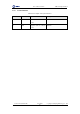
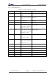
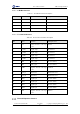
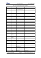
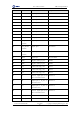
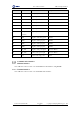
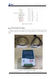
Table Of Contents
- 1. Security Precautions
- 2. Introduction
- 3. Hardware Installation
- 4. Electrical Specifications
- 5. Installation and Commissioning
- 5.1 Installing Software
- 5.2 Connecting Power Supply
- 5.3 Connecting Emergency Stop Switch
- 5.4 Connecting External Cables
- 5.5 System Commissioning
- 6. Operation
- 7. Maintenance

Dobot M1 User Guide 4 Electrical Specifications
Issue V1.0.4 (2018-08-30) User Guide Copyright © Yuejiang Technology Co., Ltd
28
4.3.2.3 CAN Bus Interface
Table 4.7 The CAN bus interface description
PIN
Name
Function
Voltage/Current
1
VBUS
Positive of VBUS
48V/5A
2
GND
Negative of VBUS
GND/5A
3
CAN1_H
CAN bus
CAN level
4
CAN1_L
CAN bus
CAN level
4.3.2.4 Forearm I/O Interface
Table 4.8 The Forearm I/O interface description
PIN
Name
Function
Voltage/Current
1
VCC
Positive electrode of the logic
power
24V/2A
2
DOUT19
Digital output
0V,24V/2mA
3
DOUT20
Digital output
0V,24V/2mA
4
DOUT21
Digital output
0V,24V/2mA
5
DOUT22
Digital output
0V,24V/2mA
6
AIN6
Analog input
0V-12V/<100mA
7
AIN7
Analog input
0V-12V/<100mA
8
AGND
Negative electrode of the logic
power
AGND/1A
9
RS485_A
RS485A bus
RS485 RS485 level
10
RS485_B
RS485B bus
RS485 RS485 level
11
DIN21
Digital input
0V,24V/<100mA
12
DIN22
Digital input
0V,24V/<100mA
13
DIN23
Digital input
0V,24V/<100mA
14
DIN24
Digital input
0V,24V/<100mA
15
GND
Negative electrode of the logic
power
GND/2A
External Expansion Interface