
Manual
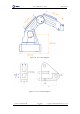

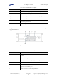


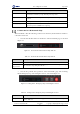
Table Of Contents
- 1. Security Precautions
- 2. Quick Start
- 3. Introduction
- 4. Interface Description
- 5. Operation
- 5.1 Introduction to the DobotStudio
- 5.2 Performing Teaching & Playback Tasks
- 5.3 Working in Offline Mode
- 5.4 Writing and Drawing
- 5.5 Performing Laser Engraving Tasks
- 5.6 Engraving a Grayscale Image
- 5.7 Controlling with your Hand Gesture
- 5.8 Controlling with your Mouse
- 5.9 Operating 3D Printing
- 5.10 Calibration
- 5.11 Connecting with WIFI Kit
- 5.12 Connecting with Bluetooth Kit
- 5.13 Operating Blockly
- 5.14 Scripting
- 5.15 Operating Stick Controller Kit
- 5.16 Operating Sliding Rail
- 5.17 Multiplexed I/O Demo
- Appendix A Dobot Magician Homing Operation

Dobot Magician User Guide 4 Interface Description
Issue V1.7.0 (2019-01-09) User Guide Copyright © Yuejiang Technology Co., Ltd.
28
Table 4.2 Peripheral interface description
Interface
Description
SW1
Power interface of air pump; output 12V of controllable power
SW2
Output 12V of controllable power
Stepper1
User-defined stepper interface; extruder interface (3D printing mode)
Stepper2
User-defined stepper interface
GP1
Signal interface of air pump; color sensor interface; infrared sensor interface;
user-defined general interface
GP2
User-defined general interface
Figure 4.2 shows the peripheral interface on the Forearm, and Table 4.3 lists the description of
the peripheral interfaces.
Figure 4.2 Peripheral interface in the Forearm
Table 4.3 Peripheral interface description
No.
Description
1
GP3, End-effector interface; R-axis servo interface; user-defined general
interface
2
GP4, Auto levelling interface, user-defined general interface
3
GP5, Signal interface of laser engraving; user-defined general interface
4
SW3, Hot end interface (3D printing mode); Output 12V of controllable power
5
SW4, Fan interface (3D printing mode); Power interface of laser engraving;
Output 12V of controllable power
6
ANALOG, Thermistor interface (3D printing mode)