
Instructions / Assembly

SINGLE “P” PROFILE
MOUNTING INSTRUCTIONS
300 New Huntington Rd, Woodbridge, ON, L4H 0R4 800-295-3625
www.dockedge.com
TOOLS & ADDITIONAL
MATERIALS REQUIRED
S.S. Mounting Screws 1006-F
Connectors 1028-F
Corners 1048-F
End Plugs 1026-F
Clear PVC Solvent 1051-F
Tape Measure
Square
Sharp Hand Saw
Mitre Box
Cordless Screw Driver
The carton this product came in is made from 100% recycled material. Please recycle again. Made and Printed in Canada.
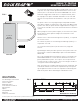
The strip can be mounted to the edge of any dock with a 2” x 4” face
or greater. The strip is held in position with Stainless Steel Screws
(1006-F). The screws must be located on a MAXIMUM of 8” centres
and can be staggered as shown in the screw pattern below, FIG. 2.
The top edge of the profile should be mounted first. The start and
finish of each strip must be fastened with 2 screws 1/2” from each
end.
The profile can be cut to any length using a sharp hand saw and a
mitre box as a guide, or a power mitre saw can be used. When using
a power mitre saw, the profile must be supported with a scrap piece
of 2 x 4 on the saw table. Use a slow controlled feed on the saw when
cutting.
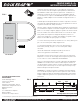
When joining one or more profile lengths, use the Connectors (1028-
F). This will line up the profiles and give the installation a clean
continuous look.
Outside corners can be formed using Corners (1048-F), 1 is required
for each 90º corner.
The ends of the profile are sealed using the End Plugs (1026-F), 1 is
required for each end.
Use Clear PVC Solvent (1051-F) on all Connectors, Plugs and
Corners.
By following the above procedure you will seal the profile and create
an internal air cushion for added impact protection. AIR CUSHION
PROFILE©
All screws should be driven flush with the surface of the profile. DO
NOT OVERTIGHTEN. The screws must be mounted in the small “v”
groove provided in the profile. Use a spacer stick or tape measure
to ensure that the screws are on 8” centres as it will give the dock a
clean, professional finished appearance.
Note: The profile has a compressed look to it before installation. This
is deliberate and will ensure that the top and side lips of the profile
lay flat against the dock face. After the top has been mounted, push
down on the profile before mounting the side bottom screws.
FIG. 1
END VIEW
2” x 4” or
greater
Dock Face
FIG. 2
8” 8”
8”
½”
8”
4”
Bottom Offset 4” From Top
SCREW PATTERN
End Plug Connector