2015 USER CHALLENGER DOWNLOAD A FREE ELECTRONIC COPY OF THE OWNER’S MANUAL AND WARRANTY BOOKLET GUIDE INCLUDES SRT 392/SRT HELLCAT BY VISITING: W W W.DODGE .COM / E N / O W NE R S / M A NU A L S OR W W W.DODGE .COM / E N / WA R R A N T Y (U.S.); W W W . O W N E R S . M O P A R . C A / E N ( C A N A D A ). DODGE AND CHALLENGER ARE REGISTERED TRADEMARKS OF CHRYSLER GROUP LLC. 15D491-926-AA C H A L L E N GE R 1848960_15d_Challenger_UG_112014.
IMPORTANT This User G u i d e i s i n t e n de d t o f a m i l i a r i z e y o u w i t h t h e i mportant features of your v e h i c l e . T h e D V D e n c l o s e d c o n t a i n s y o u r Owner’s Manual, Navi gati on / U con n ect ® M a n u a l s , Wa r r a n t y B o o k l e t s , Ti re Warranty and Roadside A s s i s t a n c e ( n e w v e h i c l e s p u r c h a s e d i n t h e U.S.) or Roadside A ssistanc e ( n e w v e h i c l e s p u r c h a s e d i n C a n a d a ) i n e l e c tronic format.
TABLE OF CONTENTS INTRODUCTION/WELCOME WELCOME FROM CHRYSLER GROUP LLC . . . . . . . . . . . . . . . . . . . . . . . 3 CONTROLS AT A GLANCE DRIVER COCKPIT . . . . . . . . . . . . . . . 6 INSTRUMENT CLUSTER . . . . . . . . . . . 8 GETTING STARTED KEY FOB . . . . . . . . . . . . . . . . . . . 10 REMOTE START . . . . . . . . . . . . . . . 13 KEYLESS ENTER-N-GO™ . . . . . . . . . 14 VEHICLE SECURITY ALARM . . . . . . . . 17 SEAT BELT SYSTEMS . . . . . . . . . . . .
TABLE OF CONTENTS CONSUMER ASSISTANCE CHRYSLER GROUP LLC CUSTOMER CENTER . . . . . . . . . . . . . . . . . . CHRYSLER CANADA INC. CUSTOMER CENTER . . . . . . . . . . . . . . . . . . ASSISTANCE FOR THE HEARING IMPAIRED . . . . . . . . . . . . . . . . . PUBLICATIONS ORDERING . . . . . . . REPORTING SAFETY DEFECTS IN THE UNITED STATES . . . . . . . . . . . . . . 2 MOPAR® ACCESSORIES . 221 AUTHENTIC ACCESSORIES BY MOPAR® . . . . . . . . . . . . . . . . . . . 223 . 221 FREQUENTLY ASKED QUESTIONS . 221 .
INTRODUCTION/WELCOME WELCOME FROM CHRYSLER GROUP LLC Congratulations on selecting your new Chrysler Group LLC vehicle. Be assured that it represents precision workmanship, distinctive styling, and high quality - all essentials that are traditional to our vehicles. Your new Chrysler Group LLC vehicle has characteristics to enhance the driver's control under some driving conditions. These are to assist the driver and are never a substitute for attentive driving. They can never take the driver's place.
INTRODUCTION/WELCOME VEHICLES SOLD IN CANADA With respect to any vehicles sold in Canada, the name Chrysler Group LLC shall be deemed to be deleted and the name Chrysler Canada Inc. used in substitution (excluding legal lines). WARNING! • Pedals that cannot move freely can cause loss of vehicle control and increase the risk of serious personal injury. • Always make sure that objects cannot fall into the driver foot well while the vehicle is moving.
INTRODUCTION/WELCOME USE OF AFTERMARKET PRODUCTS (ELECTRONICS) The use of aftermarket devices including cell phones, MP3 players, GPS systems, or chargers may affect the performance of on-board wireless features including Keyless Enter-N-Go™ and Remote Start range. If you are experiencing difficulties with any of your wireless features, try disconnecting your aftermarket devices to see if the situation improves. If your symptoms persist, please see an authorized dealer.
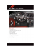
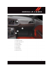
C O N T R O L S AT A G L A N C E DRIVER COCKPIT 1. Headlight Switch pg. 38 2. Driver Information Display (DID) Controls pg. 136 3. Instrument Cluster pg. 8 4. Speed Control pg. 39 5. Adaptive Cruise Control pg. 41 6. Engine Start/Stop Button pg. 16 7. Identify Your Uconnect® Radio pg. 58 8. Glove Compartment 9. Power Outlet pg.
C O N T R O L S AT A G L A N C E 10. Shift Lever 11. Emergency Flashers 12. Climate Controls pg. 50 13. Decklid Button 14. Emergency Brake 15. Hood Release 16. Power Mirrors 17. Power Windows 18.
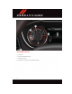
C O N T R O L S AT A G L A N C E INSTRUMENT CLUSTER 1. Tachometer 2. Indicators And Warning Lights 3. Temperature Gauge (See page 156 for Instrument Cluster Warning Lights.
C O N T R O L S AT A G L A N C E 4. Fuel Gauge And Fuel Door Locator 5. Speedometer 6. Indicator And Warning Lights (See page 162 for Instrument Cluster Indicator Lights.
GETTING STARTED KEY FOB The Key Fob contains the Remote Keyless Entry (RKE) transmitter and an emergency key, which stores in the rear of the Key Fob. The emergency key allows for entry into the vehicle should the battery in the vehicle or the Key Fob go dead. The emergency key is also for locking/unlocking the glove compartment. You can keep the emergency key with you when valet parking.
GETTING STARTED SRT Key Fobs SRT 392 Key Fob SRT Hellcat Key Fob 1 — Decklid 2 — Unlock 3 — Lock 4 — Remote Start 5 — Panic Alarm 6 — Emergency Key NOTE: SRT vehicle equipped with the 6.2L Supercharged engine come with three key fobs (two red and one black) that allow for different engine power levels. Please refer to the "Drive Modes" in “SRT” section in this guide for further descriptions Locking And Unlocking The Doors Push and release the LOCK button on the RKE transmitter to lock all doors.
GETTING STARTED Panic Alarm 1. Push the PANIC button once to turn the panic alarm on. 2. Wait approximately three seconds and push the button a second time to turn the panic alarm off. Emergency Key Should the battery in the vehicle or the Key Fob transmitter go dead, there is an emergency key located in the Key Fob that can be used for locking and unlocking the doors.
GETTING STARTED WARNING! • Never leave children alone in a vehicle, or with access to an unlocked vehicle. Allowing children to be in a vehicle unattended is dangerous for a number of reasons. A child or others could be severely injured or killed. Children should be warned not to touch the parking brake, brake pedal, or the transmission gear selector.
GETTING STARTED KEYLESS ENTER-N-GO™ The Keyless Enter-N-Go™ system is an enhancement to the vehicle's Key Fob. This feature allows you to lock and unlock the vehicle's door(s) and trunk without having to push the Key Fob lock or unlock buttons as well as starting and stopping the vehicle with the push of a button. To Unlock From The Driver Or Passenger Side: • With a valid Keyless Enter-N-Go™ Key Fob located outside the vehicle and within 5 ft (1.
GETTING STARTED • If “Unlock All Doors 1st Press” is programmed, all doors and trunk will unlock when you push the trunk button. To select between “Unlock Driver Door 1st Press” and “Unlock All Doors 1st Press,” refer to the Driver Information Display (DID) in your vehicle's Owner's Manual on the DVD or Programmable Features in this guide for further information.
GETTING STARTED Engine Starting/Stopping - Automatic Transmission Starting • Place the shift lever in PARK or NEUTRAL. • While pushing the brake pedal, push the ENGINE START/STOP button once. If the engine fails to start, the starter will disengage automatically after 10 seconds. • To stop the cranking of the engine prior to the engine starting, push the button again. Stopping • Place the shift lever in PARK. • Push the ENGINE START/STOP button 1 – Start/Stop Button once.
GETTING STARTED Additional Functions NOTE: The following functions are with the driver’s foot OFF the Brake Pedal/Clutch Pedal (Transmission in PARK or NEUTRAL Position). Starting With The Ignition Switch In The OFF Position: • Push the ENGINE START/STOP button once to change the ignition switch to the ACC position. • Push the ENGINE START/STOP button a second time to change the ignition switch to the RUN position.
GETTING STARTED To Disarm • Keyless Enter-N-Go™ button installed: Push the Key Fob UNLOCK button or with one of the Key Fobs located outside the vehicle and within 5 ft (1.5 m) of the driver's and passenger front door handles, grab the Keyless Enter-N-Go™ door handle and enter the vehicle, then push the Keyless Enter-N-Go™ START/STOP button (requires at least one valid Key Fob in the vehicle).
GETTING STARTED SUPPLEMENTAL RESTRAINT SYSTEM (SRS) — AIR BAGS Air Bag System Components Your vehicle may be equipped with the following air bag system components: • Occupant Restraint Controller (ORC) • Air Bag Warning Light • Steering Wheel and Column • Instrument Panel • Knee Impact Bolsters • Advanced Front Air Bags • Supplemental Side Air Bags • Front and Side Impact Sensors • Seat Belt Pretenioners • Seat Belt Buckle Switch • Seat Track Position Sensors Advanced Front Air Bags • This vehicle has Adva
GETTING STARTED • The ORC turns on the Air Bag Warning Light in the instrument panel for approximately four to eight seconds for a self-check when the ignition switch is first turned to the ON/RUN position. After the self-check, the Air Bag Warning Light will turn off. If the ORC detects a malfunction in any part of the system, it turns on the Air Bag Warning Light, either momentarily or continuously. A single chime will sound to alert you if the light comes on again after initial startup.
GETTING STARTED WARNING! • Side Air Bags need room to inflate. Do not lean against the door or window. Sit upright in the center of the seat. • Being too close to the Side Air Bags during deployment could cause you to be severely injured or killed. • Relying on the Side Air Bags alone could lead to more severe injuries in a collision. The Side Air Bags work with your seat belt to restrain you properly. In some collisions, Side Air Bags won’t deploy at all.
GETTING STARTED LATCH System Weight Limit You may use the LATCH anchorage system until the combined weight of the child and the child restraint is 65 lbs (29.5 kg). Use the seat belt and tether anchor instead of the LATCH system once the combined weight is more than 65 lbs (29.5 kg). Locating LATCH Anchorages The lower anchorages are round bars that are found at the rear of the seat cushion where it meets the seatback, below the anchorage symbols on the seatback.
GETTING STARTED Installing The Child Restraint Using The LATCH Lower Anchors NOTE: Never “share” a LATCH anchorage with two or more child restraints. 1. Loosen the adjusters on the lower straps and on the tether strap of the child seat so that you can more easily attach the hooks or connectors to the vehicle anchorages. 2. Attach the lower hooks or connectors of the child restraint to the lower anchorages in the selected seating position. 3.
GETTING STARTED 7. If the child restraint has a top tether strap and the seating position has a top tether anchorage, connect the tether strap to the anchorage and tighten the tether strap. See below for directions to attach a tether anchor. 8. Test that the child restraint is installed tightly by pulling back and forth on the child seat at the belt path. It should not move more than 1 inch (25.4 mm) in any direction.
GETTING STARTED WARNING! • In a collision, an unrestrained child, even a tiny baby, can become a projectile inside the vehicle. The force required to hold even an infant on your lap could become so great that you could not hold the child, no matter how strong you are. The child and others could be severely injured or killed. Any child riding in your vehicle should be in a proper restraint for the child's size.
GETTING STARTED To remove the head restraint, remove the seat belt from the seat belt loop. Raise the head restraint as far as it can go then push the adjustment button and the release button at the base of each post while pulling the head restraint up. To reinstall the head restraint, put the head restraint posts into the holes while pushing the adjustment button and release button. Then adjust it to the appropriate height.
GETTING STARTED Power Lumbar • Push the switch forward to increase the lumbar support. Push the switch rearward to decrease the lumbar support. • Pushing upward or downward on the switch will raise and lower the position of the support. Power Lumbar Switch Manual Seat Adjustment Forward/Rearward • Lift up on the adjusting bar located at the front of the seat near the floor and release it when the seat is at the desired position.
GETTING STARTED Recliner • Lean forward in the seat and lift the recliner lever, then lean back to the desired position and release the lever. • Lift the lever to return the seatback to an upright position. Recliner Handle Easy Entry Seats • Pull forward on the lever, located on the side of the seatback, to dump the seatback forward and slide the seat forward. You can also temporarily remove the seat belt from the guide loop on the seat and allow the seat belt to retract out of the way.
GETTING STARTED WARNING! • Adjusting a seat while the vehicle is moving is dangerous. The sudden movement of the seat could cause you to lose control. The seat belt might not be properly adjusted, and you could be severely injured or killed. Only adjust a seat while the vehicle is parked. • Do not ride with the seatback reclined so that the seat belt is no longer resting against your chest. In a collision, you could slide under the seat belt and be severely injured or killed.
GETTING STARTED HEATED/VENTILATED SEATS Front Heated Seats The front heated seats control buttons are located within the climate or controls screen of the touchscreen. • Press the heated seat button once to turn the HI setting On. • Press the heated seat button a second time to turn the LO setting On. • Press the heated seat button a third time to turn the heating elements OFF. If the HI-level setting is selected, the system will automatically switch to LO-level after approximately 60 minutes.
GETTING STARTED To operate the system, press the “Controls” button on touchscreen located on the bottom of the Uconnect® display. • Press the ventilated seat button once to choose HI. • Press the ventilated seat button a second time to choose LO. • Press the ventilated seat button a third time to turn the ventilated seat OFF. NOTE: On models that are equipped with remote start, this feature can be programmed to come on during a remote start through the Uconnect® system.
GETTING STARTED TILT/TELESCOPING STEERING COLUMN Manual Tilt/Telescoping Steering Column • The tilt/telescoping control handle is located below the steering wheel at the end of the steering column. • To unlock the steering column, push the lever downward (toward the floor). • To tilt the steering column, move the steering wheel upward or downward as desired. • To lengthen or shorten the steering column, pull the steering wheel outward or push it inward as desired.
GETTING STARTED WARNING! • Do not adjust the steering wheel while driving. The tilt/telescoping adjustment must be locked while driving. Adjusting the steering wheel while driving or driving without the tilt/telescoping adjustment locked could cause the driver to lose control of the vehicle. Failure to follow this warning may result in you and others being severely injured or killed. • Moving the steering column while the vehicle is moving is dangerous.
O P E R AT I N G Y O U R V E H I C L E ENGINE BREAK-IN RECOMMENDATIONS For vehicles equipped with the 3.6L or 5.7L use the following engine break-in recommendations: A long break-in period is not required for the drivetrain (engine, transmission, clutch, and rear axle) in your new vehicle. Drive moderately during the first 300 mi (500 km). After the initial 60 mi (100 km), speeds up to 50 or 55 mph (80 or 90 km/h) are desirable.
O P E R AT I N G Y O U R V E H I C L E 100 to 300 miles (161 to 483 km): • Depress the accelerator pedal slowly and not more than halfway to avoid rapid acceleration in lower gears (1st to 3rd gears). • Avoid aggressive braking. • Drive with the engine speed less than 5,000 RPM. • Maintain vehicle speed below 70 mph (112 km/h) and observe local speed limits. 300 to 500 miles (483 to 805 km): • Exercise the full engine rpm range, shifting manually (paddles or gear shift) at higher rpms when possible.
O P E R AT I N G Y O U R V E H I C L E 300 to 500 miles (483 to 805 km): • Exercise the full engine rpm range, shifting manually (paddles or gear shift) at higher rpms when possible. • Do not perform sustained operation with the accelerator pedal at wide open throttle. • Maintain vehicle speed below 85 mph (136 km/h) and observe local speed limits. For the first 1500 mi (2414 km): • Do not participate in track events, sport driving schools, or similar activities during the first 1500 mi (2414 km).
O P E R AT I N G Y O U R V E H I C L E Front Wipers Intermittent, Low And High Operation Rotate the end of the lever to the first detent position for one of four intermittent settings, the second detent for low wiper operation and the third detent for high wiper operation. Mist Rotate the end of the lever rearward when a single wipe is desired. NOTE: The mist feature does not activate the washer pump; therefore, no washer fluid will be sprayed on the windshield.
O P E R AT I N G Y O U R V E H I C L E HEADLIGHT SWITCH Automatic Headlights/Parking Lights/Headlights • Rotate the headlight switch, located on the instrument panel to the left of the steering wheel, to the first detent from the off position for parking light and to the second detent for headlight . • With the parking lights or low beam headlights on, push the headlight switch for front fog lights. Pushing the switch a second time will deactivate the front fog lights.
O P E R AT I N G Y O U R V E H I C L E Ambient Light Dimmer • Rotate the ambient light control up or down to increase or decrease the brightness of the release handle, map pocket (if equipped), overhead and floor lighting when the parking lights or headlights are on. • Rotate to extreme bottom position to turn off. ELECTRONIC SPEED CONTROL The Electronic Speed Control switches are located on the right side of the steering wheel.
O P E R AT I N G Y O U R V E H I C L E The drivers preferred units can be selected through the instrument panel settings if equipped. Refer to “Understanding Your Instrument Panel” in the Owner’s Manual on the DVD for more information. The speed increment shown is dependant on the speed of U.S. (mph) or Metric (km/h) units: U.S. Speed (mph) • Pushing the SET + button once will result in a 1 mph increase in set speed. Each subsequent tap of the button results in an increase of 1 mph.
O P E R AT I N G Y O U R V E H I C L E WARNING! Leaving the Electronic Speed Control system on when not in use is dangerous. You could accidentally set the system or cause it to go faster than you want. You could lose control and have an accident. Always leave the system OFF when you are not using it. ADAPTIVE CRUISE CONTROL (ACC) If your vehicle is equipped with adaptive cruise control the controls operate exactly the same as the electronic speed control with only a couple of differences.
O P E R AT I N G Y O U R V E H I C L E U.S. Speed (mph) • Pushing the SET + button once will result in a 1 mph increase in set speed. Each subsequent tap of the button results in an increase of 1 mph. • If the button is continually pushed, the set speed will continue to increase in 5 mph increments until the button is released. The increase in set speed is reflected in the DID. Metric Speed (km/h) • Pushing the SET + button once will result in a 1 km/h increase in set speed.
O P E R AT I N G Y O U R V E H I C L E • The ACC system maintains set speed when driving up hill and down hill. However, a slight speed change on moderate hills is normal. In addition, downshifting may occur while climbing uphill or descending downhill. This is normal operation and necessary to maintain set speed. When driving up hill and down hill, the ACC system will cancel if the braking temperature exceeds normal range (overheated).
O P E R AT I N G Y O U R V E H I C L E WARNING! Adaptive Cruise Control (ACC) is a convenience system. It is not a substitute for active driving involvement. It is always the driver’s responsibility to be attentive of road, traffic, and weather conditions, vehicle speed, distance to the vehicle ahead; and, most importantly, brake operation to ensure safe operation of the vehicle under all road conditions. Your complete attention is always required while driving to maintain safe control of your vehicle.
O P E R AT I N G Y O U R V E H I C L E FORWARD COLLISION WARNING (FCW) WITH MITIGATION The Forward Collision Warning (FCW) system with mitigation provides the driver with audible warnings, visual warnings (within the DID), and may apply a brake jerk to warn the driver when it detects a potential frontal collision. The warnings and limited braking are intended to provide the driver with enough time to react, avoid or mitigate the potential collision.
O P E R AT I N G Y O U R V E H I C L E Far The default status of FCW is the “Far” setting. The far setting provides warnings for potential collisions more distant in front of the vehicle, allowing the driver to have the most reaction time to avoid a collision. This setting is designed to provide early warnings per NHTSA (National Highway Traffic Safety Administration) recommendations. More cautious drivers that do not mind frequent warnings may prefer this setting.
O P E R AT I N G Y O U R V E H I C L E PARKSENSE® REAR PARK ASSIST The four ParkSense® sensors, located in the rear fascia/bumper, monitor the area behind the vehicle that is within the sensors’ field of view. The sensors can detect obstacles from approximately 12 in (30 cm) up to 79 in (200 cm) from the rear bumper while the vehicle is in REVERSE, a warning will display in the Driver Information Display (DID) only when (Sound and Display is selected from the Uconnect® System).
O P E R AT I N G Y O U R V E H I C L E In AutoStick mode, the transmission will shift up or down when (+/-) is manually selected by the driver (using the shift lever, or the shift paddles [if equipped]), unless an engine lugging or overspeed condition would result. It will remain in the selected gear until another upshift or downshift is chosen, except as described below. • In temporary AutoStick mode (shift lever in DRIVE), the transmission will automatically shift up when maximum engine speed is reached.
O P E R AT I N G Y O U R V E H I C L E SPORT MODE — WITHOUT PERFORMANCE CONTROL Your vehicle is equipped with a Sport Mode feature. This mode is a configuration set up for typical enthusiast driving. The engine, transmission (when equipped with automatic transmission), and steering systems are all set to their SPORT settings. Sport Mode will provide improved throttle response and modified shifting for an enhanced driving experience, as well the greatest amount of steering feel.
O P E R AT I N G Y O U R V E H I C L E AUTOMATIC TEMPERATURE CONTROLS (ATC) Uconnect® 5.
O P E R AT I N G Y O U R V E H I C L E Uconnect® 8.
O P E R AT I N G Y O U R V E H I C L E Automatic Climate Control Knobs 1 — FRONT Defroster Button 2 — Driver Temperature Up 3 — Blower Control Knob 4 — OFF Button 5 — Passenger Temperature Up 6 — A/C Button 7 — Air Recirculation Button 8 — Passenger Temperature Down 9 — AUTO Button 10 — Driver Temperature Down 11 — Rear Window Defroster Button Automatic Operation The climate system will automatically adjust settings to achieve and maintain comfort. • Press the AUTO button.
O P E R AT I N G Y O U R V E H I C L E MAX A/C MAX A/C sets the control for maximum cooling performance. • Press and release to toggle between MAX A/C and the prior settings. The button on the touchscreen illuminates when MAX A/C is ON. In MAX A/C, the blower level and mode position can be adjusted to desired user settings. Pressing other settings will cause the MAX A/C operation to switch to the prior settings and the MAX A/C indicator will turn off.
O P E R AT I N G Y O U R V E H I C L E BLIND SPOT MONITORING The Blind Spot Monitoring (BSM) system uses two radar-based sensors, located inside the rear bumper fascia, to detect Highway licensable vehicles (automobiles, trucks, motorcycles etc.) that enter the blind spot zones from the rear/front/side of the vehicle. The Blind Spot Monitoring (BSM) system warning light, located in the outside mirrors, will illuminate if a vehicle moves into a blind spot zone.
O P E R AT I N G Y O U R V E H I C L E Pinch Protection Feature • This feature will detect an obstruction in the opening of the sunroof during Express Close operation. If an obstruction in the path of the sunroof is detected, the sunroof will automatically retract. Remove the obstruction if this occurs. Next, push the switch forward and release to Express Close.
ELECTRONICS YOUR VEHICLE'S SOUND SYSTEM 1. Uconnect® Phone Button pg. 125 2. Uconnect® Voice Command Button pg. 98 3. Uconnect® Phone Hang Up Button pg. 98 4. Steering Wheel Audio control (Left) pg. 135 5. Steering Wheel Audio control (Right) pg. 135 6.
ELECTRONICS 7. Uconnect® 8.4 Radio pg. 86 8. Back Button 9. Tune/Scroll Knob – Browse/Enter Button 10. Power Outlet pg. 144 11. AUX/SD Card/USB Port (Located In Center Console) pg.
ELECTRONICS IDENTIFYING YOUR RADIO Uconnect® 5.0 • 5” Touchscreen • Three buttons on the faceplates on either side of the display Uconnect® 5.0 Uconnect® 8.4A • 8.4” Touchscreen • Climate button on the touchscreen in lower menu bar • HD Button will NOT be visible on right side of screen when viewing AM or FM • SiriusXM Travel Link feature NOT listed within Apps Uconnect® 8.4A Uconnect® 8.4AN • 8.
ELECTRONICS Uconnect® ACCESS Uconnect® Access — If Equipped (Available On Uconnect® 8.4A/8.4AN — U.S. Residents Only) WARNING! ALWAYS drive safely with your hands on the steering wheel. You have full responsibility and assume all risks related to the use of the Uconnect® features and applications in this vehicle. Only use Uconnect® when it is safe to do so. Failure to do so may result in an accident involving serious injury or death.
ELECTRONICS 3. The Uconnect® Voice Command and Uconnect® Phone buttons are located on the left side of your steering wheel. These buttons let you use your voice to give commands, make phone calls, send and receive text messages hands-free, enter navigation destinations, and control your radio and media devices.
ELECTRONICS NOTE: For security reasons, this link is valid for 72 hours from the time you’ve submitted your email address into the radio touchscreen. If the link has expired, simply re-enter your email address into the Uconnect® Registration App on the radio touchscreen to receive another link. The secured registration link will take you through the Uconnect® Access registration process step by step. 7.
ELECTRONICS Set Up Your Via Mobile Profile — If Equipped Setting up your Via Mobile profile means entering your login information for each App so that they can work in your vehicle. Complete your Via Mobile Profile online during registration of your Uconnect® Access system. Access this page by logging into your Mopar Owner Connect account (moparownerconnect.com), going to Edit Profile, then Via Mobile Profile.
ELECTRONICS 3. From the Uconnect® Store, select the item you wish to purchase. 4. This will launch the selected item into purchase mode along with providing additional information. 5. The Uconnect® Store will display a “Purchase Overview” message confirming the financial details of your purchase. Click the “Purchase” key to continue. 6. The Uconnect® Store will ask you to “Confirm Payment” using your default payment method on file in your Payment Account. Click the “Complete” key to continue. 7.
ELECTRONICS 2. Uconnect® Access Via Mobile (if equipped) — Via Mobile uses the Uconnect® Access app and your smartphone's data plan to access your personal Pandora®, iHeartRadio, Aha™ by HARMAN and Slacker Radio accounts from the vehicle and control them using the vehicle touchscreen. Customer’s data plan charges will apply. Available on Uconnect® 8.4A and 8.4AN Radios (if equipped).
ELECTRONICS Maintaining Your Uconnect® Access Account Reinstalling An App (Uconnect® 8.4A/8.4AN) You can easily correct many Application related issues you may be experiencing by resetting the App back to the factory setting. From the vehicle’s radio touchscreen, complete the following steps: 1. Press the Uconnect® “Apps” button and open the Uconnect® Store. Go to My Apps. 2. In My Apps, select “Settings,” then “Reinstall App.” Press “Continue.” 3. Your Apps have been successfully re-installed.
ELECTRONICS Built-In Features (Uconnect® 8.4A/8.4AN) CAUTION! • Ignoring the rearview mirror light could mean you may not have 9-1-1 Call service if needed. If the rearview mirror light is illuminated, have an authorized dealer service the 9-1-1 Call system immediately. • The Occupant Restraint Controller (ORC) turns on the Air Bag Warning Light on the instrument panel if a malfunction is detected in any part of the air bag system.
ELECTRONICS 2. Emergency 9-1-1 Call (If Equipped) — The rearview mirror contains a 9-1-1 button that, when pressed, may place a call from your vehicle to a local 9-1-1 operator to request help from local police, fire or ambulance personnel. If this button is accidentally pushed, you will have 10 seconds to stop the call. To cancel, push the 9-1-1 Call button again or press the “cancel” button shown on the touchscreen.
ELECTRONICS and the built-in wireless connection within your vehicle, the Uconnect® Care agent will be able to locate the stolen vehicle and work with law enforcement to help recover it. (Vehicle must be within the United States, have network coverage and must be registered with Uconnect® Access with an active subscription that includes the applicable feature). 7. WiFi Hotspot — WiFi Hotspot is on-demand WiFi 3G connectivity that's built-in and ready to go whenever you are.
ELECTRONICS Remote Door Lock/Unlock — This feature provides the ability to lock or unlock the door on your vehicle, without the keys and from virtually any distance. You can send a request to your vehicle in one of three ways: 1. Using the Uconnect® Access App from a compatible smartphone. 2. From the Mopar Owner Connect website. 3. By contacting the Uconnect® Care on the phone. To use this feature after the Uconnect® Access App is downloaded, login using your user name and password.
ELECTRONICS To Send A Text Message: 1. Push the Uconnect® Phone Button on the steering wheel. 2. Wait for the beep. 3. Say “Text.” 4. Uconnect® will prompt you “Say the phone number, or full name and phone type of the contact you want to send a message to.” 5. Wait for the beep and say a contact that is in your phonebook, or a mobile phone number that you would like to send the message to. 6. Uconnect® will prompt you “Please say the message that you would like to send.
ELECTRONICS Uconnect® Access Via Mobile — If Equipped (Available On Uconnect® 8.4A/8.4AN) Via Mobile uses the Uconnect® Access app and your smartphone's data plan to access your personal Pandora®, iHeartRadio, Aha™ by HARMAN and Slacker Radio accounts from the vehicle and control them using the vehicle touchscreen. Customer’s data plan charges will apply.
ELECTRONICS Each time you want to use a Via Mobile app in your vehicle, the Uconnect® Access App must be running on your smartphone and the smartphone must be paired via Bluetooth®.
ELECTRONICS If equipped, the Via Mobile apps can be found by selecting the “Apps” button on the touchscreen in the lower right corner of the radio touchscreen. Via Mobile apps are listed under the “All Apps” tab. The words “Via Mobile” will appear after the app name indicating it is a Via Mobile app. All Apps 1 — Catagory Tabs 2 — Apps Button Via Mobile apps can also be launched through Voice Recognition by pressing the VR button on the steering wheel and stating “launch” and then the name of the app.
ELECTRONICS A message will be displayed to remind you that Via Mobile apps utilize the data plan on your connected smartphone to provide content. Many smartphones have a limit to how much data they can utilize before incurring additional charges. The amount of data being used varies by smartphone device, cellular service provider and specific app. Check your mobile phone service plan for more details.* Press “OK” to continue or the “X” to exit. (*Additional smartphone data usage charges may apply.
ELECTRONICS Uconnect® 5.0 Uconnect® 5.0 1 — RADIO Mode Button 2 — Presets Button 3 — COMPASS Information Button 4 — CLIMATE Function Button 5 — + MORE Function Button 6 — Audio Button 7 — Info Button 8 — Manual Tune Button 9 — AM/FM/SXM Button 10 — SEEK Up Button 11 — SEEK Down Button 12 — Uconnect® PHONE Button 13 — MEDIA Mode Button Clock Setting To start the clock setting procedure: 1. Push the + MORE button on the faceplate.
ELECTRONICS Equalizer, Balance And Fade To adjust the Audio settings: 1. Push the + MORE button on the faceplate, then press the “Settings” button on the touchscreen. 2. Scroll down and press the “Audio” button on the touchscreen to open the Audio menu. The Audio Menu shows the following options for you to customize your audio settings. Equalizer • Press the “Equalizer” button on the touchscreen to adjust the Bass, Mid and Treble.
ELECTRONICS SiriusXM Premier Over 160 channels Get every channel available on your satellite radio, and enjoy all you want, all in one place. Hear commercial-free music plus sports, news, talk and entertainment. Get all the premium programming, including Howard Stern, every NFL game, Oprah Radio®, every MLB® and NHL® game, every NASCAR® race, Martha Stewart and more.
ELECTRONICS Bluetooth® If using a Bluetooth® - equipped device, you may also be able to stream music to your vehicle's sound system. • Push the MEDIA button on the faceplate, then press the “source” button on the touchscreen. Select “Bluetooth” to change the mode to Bluetooth® if the device is paired, allowing the music from your portable device to play through the vehicle's speakers. SD Card SD Card Mode allows you to play music that has been saved to your SD Card through your vehicle’s sound system.
ELECTRONICS NOTE: Voice texting reply and voice texting features require a compatible mobile device enabled with Bluetooth® Message Access Profile (MAP). iPhone® and some other smartphones do not currently support Bluetooth® MAP. Visit UconnectPhone.com for system and device compatibility. Want to dictate a personal message? You must first register with Uconnect® Access (U.S. residents only) to take advantage of a new, cloud-based Voice Texting service, an enhancement to Voice Text Reply. Uconnect® 5.
ELECTRONICS 3. Speak clearly at a normal pace and volume while facing straight ahead. The microphone is positioned on the rearview mirror and aimed at the driver. 4. Each time you give a Voice Command, you must first push either the VR or Phone button, wait until after the beep, then say your Voice Command. 5. You can interrupt the help message or system prompts by pushing the VR or Phone button and saying a Voice Command from current category.
ELECTRONICS Basic Voice Commands The basic Voice Commands below can be given at any point while using your Uconnect® system. Push the VR button . After the beep, say: • Cancel to stop a current voice session • Help to hear a list of suggested Voice Commands • Repeat to listen to the system prompts again Notice the visual cues that inform you of your voice recognition system’s status. Cues appear on the touchscreen. Uconnect® 5.
ELECTRONICS Radio Use your voice to quickly get to the AM, FM or SiriusXM™ Satellite Radio® stations you would like to hear. (Subscription or included SiriusXM™ Satellite Radio trial required.) Push the VR button . After the beep, say: • Tune to ninety-five-point-five FM • Tune to Satellite Channel Hits 1 TIP: At any time, if you are not sure of what to say or want to learn a Voice Command, push the VR button and say “Help.” The system will provide you with a list of commands. Uconnect® 5.
ELECTRONICS Media Uconnect® offers connections via USB, SD, Bluetooth® and auxiliary ports (If Equipped). Voice operation is only available for connected USB and iPod® devices. (Remote CD player optional and not available on all vehicles.) . After the beep, say one of the following commands and Push the VR button follow the prompts to switch your media source or choose an artist.
ELECTRONICS Phone Making and answering hands-free phone calls is easy with Uconnect®. When the Phonebook button is illuminated on your touchscreen, your system is ready. U.S. residents can visit UconnectPhone.com to check mobile device and feature compatibility and to find phone pairing instructions. Push the Phone button .
ELECTRONICS Voice Text Reply Uconnect® will announce incoming text messages. Push the Phone button Listen. (Must have compatible mobile phone paired to Uconnect® system.) 1. Once an incoming text message is read to you, push the Phone button beep, say: Reply. and say . After the 2. Listen to the Uconnect® prompts. After the beep, repeat one of the pre-defined messages and follow the system prompts.
ELECTRONICS Uconnect® 8.4A Uconnect® 8.4A — If Equipped At A Glance Uconnect® 8.4A 1 — Status Bar 2 — Menu Bar 3 — Uconnect® Apps Button 4 — Uconnect® Phone Button 5 — Climate Button 6 — Controls Button 7 — Media Button 8 — Radio Button Displaying The Time If the time is not currently displayed on the radio or player main page: 1. Press the “Controls” button on the touchscreen or the “Apps” button on the touchscreen, then the “Settings” button on the touchscreen. 2.
ELECTRONICS Setting The Time Model 8.4AN synchronizes time automatically via GPS, so it should not require any time adjustment. If you do need to set the time manually, follow the instructions below for Model 8.4A. 1. Turn the unit on, then press the “Time Display” at the top of the screen. Press “Yes.” NOTE: If the time is not displayed at the top of the screen, press the “Controls” or the “Apps” button on the touchscreen, then the “Settings” button on the touchscreen.
ELECTRONICS Equalizer To adjust the equalizer settings: 1. Press the “Media” or “Radio” button on the touchscreen. 2. Press the “Audio” button on the touchscreen to activate the Audio settings screen to adjust Balance/Fade, Equalizer and Speed Adjusted Volume. 3. Press the “Equalizer” button on the touchscreen to activate the Equalizer screen. 4. Press the “+” or “–” button on the touchscreens, or by pressing and dragging over the “level bar” for each of the equalizer bands.
ELECTRONICS RADIO Uconnect® 8.4A Radio 1 — Radio Station Presets 2 — Toggle Between Presets 3 — Audio Setting 4 — Seek Up 5 — Direct Tune To A Radio Station 6 — Seek Down 7 — Browse And Manage Presets 8 — Choose Radio Band To access the Radio mode: • Press the “Radio” button at the lower left of the touchscreen. Selecting Radio Stations • Press the desired radio band (AM, FM or SXM) button on the touchscreen.
ELECTRONICS Direct Tune • Tune directly to a radio station by pressing the “Tune” button on the screen, and entering the desired station number. Store Radio Presets Your radio can store 36 total preset stations, 12 presets per band (AM, FM and SXM). They are shown at the top of your radio screen. • To see the 12 preset stations per band, press the “arrow” button on the touchscreen at the top right of the screen to toggle between the two sets of six presets.
ELECTRONICS Fav Activates the favorites menu. You can add up to 50 favorite artists or songs. • Just press Add Fav Artist or Add Fav Song while the song is playing. You will then be alerted any time one of these songs, or works by these artists, is playing on other SiriusXM channels. SiriusXM Parental Controls You can skip or hide certain channels from view if you do not want access to them. • Press the “Apps” button on the touchscreen, then the “Settings” button on the touchscreen.
ELECTRONICS Replay Lets you replay up to 44 minutes of the content of the current SiriusXM channel. Replay Option Play/Pause Rewind/RW Fast Forward/FW Replay Time Live Option Description Press to Pause content playback. Press Pause/Play again to resume playback. Rewinds the channel content in steps of five seconds. Press and hold to rewind continuously, then release to begin playing content at that point. Forwards the content, and works similarly to Rewind/RW.
ELECTRONICS The iPod® battery charges when plugged into the USB port (if supported by the specific device). There are also two USB Charge Only ports located on the back of the center console for rear passengers. To route the USB/iPod® cable out of the center console, use the access cut out. NOTE: • When connecting your iPod® device for the first time, the system may take several minutes to read your music, depending on the number of files.
ELECTRONICS iPod®/CD/AUX CONTROLS Uconnect® 8.4A Media 1 — Repeat Music Track 2 — Music Track And Time 3 — Shuffle Music Tracks 4 — Music Track Information 5 — Show Songs Currently In Cue To Be Played 6 — Browse Music By 7 — Music Source • The iPod®/CD/AUX controls are accessed by pressing the desired button displayed on the side of the touchscreen and choosing between Disc, AUX, iPod®, or Bluetooth®.
ELECTRONICS Changing The Navigation Voice Prompt Volume 1. Press the “Settings” button on the touchscreen. 2. In the Settings menu, press the “Guidance” button on the touchscreen. 3. In the Guidance menu, adjust the Nav Volume by pressing the “+” or “–” Nav Volume Adjustment button on the touchscreen. Uconnect® 8.
ELECTRONICS Finding A Place By Spelling The Name From the Main Navigation Menu press the “Where to?” button on the touchscreen, press the “Points of Interest” button on the touchscreen and then press the “Spell Name” button on the touchscreen. • Enter the name of your destination. • Press the “List” button on the touchscreen. • Select your destination and press the “Yes” button on the touchscreen.
ELECTRONICS Go Home A Home location must be saved in the system. From the Main Navigation menu, press the “Where To?” button on the touchscreen, then press the “Go Home” button on the touchscreen. Uconnect® 8.4 Map 1 — Distance To Next Turn 2 — Next Turn Street 3 — Estimated Time Of Arrival 4 — Zoom In And Out 5 — Your Location On The Map 6 — Navigation Main Menu 7 — Current Street Location 8 — Navigation Routing Options Your route is marked with a blue line on the map.
ELECTRONICS Taking A Detour To take a detour you must be navigating a route. • Press the “Detour” button on the touchscreen. NOTE: If the route you are currently taking is the only reasonable option, the device might not calculate a detour. For more information, see your Uconnect® Supplement Manual. Uconnect® 8.4A/8.4AN VOICE RECOGNITION QUICK TIPS Introducing Uconnect® Start using Uconnect® Voice Recognition with these helpful quick tips.
ELECTRONICS Get Started 1. Visit UconnectPhone.com to check mobile device and feature compatibility and to find phone pairing instructions. 2. Reduce background noise. Wind and passenger conversations are examples of noise that may impact recognition. 3. Speak clearly at a normal pace and volume while facing straight ahead. The microphone is positioned on the rearview mirror and aimed at the driver. 4.
ELECTRONICS Basic Voice Commands The basic Voice Commands below can be given at any point while using your Uconnect® system. Push the VR button . After the beep, say: • Cancel to stop a current voice session • Help to hear a list of suggested Voice Commands • Repeat to listen to the system prompts again Notice the visual cues that inform you of your voice recognition system’s status. Cues appear on the touchscreen. Uconnect® 8.4A/8.
ELECTRONICS Radio Use your voice to quickly get to the AM, FM or SiriusXM™ Satellite Radio® stations you would like to hear. (Subscription or included SiriusXM™ Satellite Radio trial required.) Push the VR button . After the beep, say: • Tune to ninety-five-point-five FM • Tune to Satellite Channel Hits 1 TIP: At any time, if you are not sure of what to say or want to learn a Voice Command, push the VR button and say “Help.” The system will provide you with a list of commands. Uconnect® 8.4A/8.
ELECTRONICS Media Uconnect® offers connections via USB, SD, Bluetooth® and auxiliary ports (If Equipped). Voice operation is only available for connected USB and iPod® devices. (Remote CD player optional and not available on all vehicles.) Push the VR button . After the beep, say one of the following commands and follow the prompts to switch your media source or choose an artist.
ELECTRONICS Phone Making and answering hands-free phone calls is easy with Uconnect®. When the Phonebook button is illuminated on your touchscreen, your system is ready. U.S. residents can visit: • UconnectPhone.com for mobile phone compatibility and pairing instructions. Canadian residents can visit: • UconnectPhone.com for mobile phone compatibility and pairing instructions. Push the Phone button .
ELECTRONICS Climate (8.4A/8.4AN) Too hot? Too cold? Adjust vehicle temperatures hands-free and keep everyone comfortable while you keep moving ahead. (If vehicle is equipped with climate control.) Push the VR button . After the beep, say one of the following commands: • Set driver temperature to 70 degrees • Set passenger temperature to 70 degrees TIP: Voice Command for Climate may only be used to adjust the interior temperature of your vehicle.
ELECTRONICS TIP: To start a POI search, push the VR button coffee shop.” . After the beep, say “Find nearest Uconnect® 8.4A/8.4AN Navigation Uconnect® Access — If Equipped (8.4A/8.4AN) An included trial and/or subscription is required to take advantage of the Uconnect® Access services in the next section of this guide. To register with Uconnect® Access, press the “Apps” button on the 8.4-inch touchscreen to get started. Detailed registration instructions can be found on the next page.
ELECTRONICS Register (8.4A/8.4AN) 1. Press the “Apps” button on the bottom of the 8.4-inch touchscreen. 2. If a pop-up message appears, press “Register” or go to the “Favorite Apps” or “All Apps” menu and press “Uconnect® Registration.” 3. Read through the registration instructions. Enter and confirm your personal email address. Then press “Send.” 4. Check your personal inbox for an email from Uconnect® Access. 5.
ELECTRONICS 2. On the Dashboard page, enter your mobile phone number to receive a link to download the App on your mobile device. Or, go to iTunes® or Google Play and search for the Uconnect® Access App. 3. To activate the App, enter your Mopar Owner Connect user name and password and log in. Your vehicle is then connected to your mobile device. Mobile App Voice Texting (8.4A/8.
ELECTRONICS Yelp® (8.4A/8.4AN) Once registered with Uconnect® Access, you can use your voice to search for the most popular places or things around you. 1. Push the VR button . After the beep, say: Launch YELP®. 2. Once the YELP® home screen appears on the touchscreen, push the VR button , then say: YELP® search. 3. Listen to the system prompts and after the beep, tell Uconnect® the place or business that you’d like Uconnect® to find.
ELECTRONICS SiriusXM Travel Link™ (8.4A/8.4AN — US Market Only) Need to find a gas station, view local movie listings, check a sports score or the 5 - day weather forecast? SiriusXM Travel Link™ is a suite of services that brings a wealth of information right to your Uconnect® 8.4AN system. (Not available for 8.4A system.) Push the VR button .
ELECTRONICS Additional Information © 2014 Chrysler Group LLC. All rights reserved. Mopar, Mopar Owner Connect and Uconnect are registered trademarks of Chrysler Group LLC. Android is a trademark of Google Inc. SiriusXM and all related marks and logos are trademarks of SiriusXM Radio Inc. Yelp, Yelp logo, Yelp burst and related marks are registered trademarks of Yelp. Uconnect® System Support: • U.S. residents visit DriveUconnect.com or call: 1-877-855-8400 • Canadian residents visit DriveUconnect.
ELECTRONICS Uconnect® 8.4AN Uconnect® 8.4AN — If Equipped At A Glance Uconnect® 8.4AN 1 — Status Bar 2 — View Small Navigation Map 3 — HD Radio Available 4 — Uconnect® Apps Button 5 — Uconnect® Phone Button 6 — Uconnect® Navigation Button 7 — Climate Button 8 — Controls Button 9 — Media Button 10 — Radio Button Displaying The Time If the time is not currently displayed on the radio or player main page: 1.
ELECTRONICS Setting The Time Model 8.4AN synchronizes time automatically via GPS, so it should not require any time adjustment. If you do need to set the time manually, follow the instructions below for Model 8.4A. 1. Turn the unit on, then press the “Time Display” at the top of the screen. Press “Yes.” NOTE: If the time is not displayed at the top of the screen, press the “Controls” or the “Apps” button on the touchscreen, then the “Settings” button on the touchscreen.
ELECTRONICS Speed Adjusted Volume To adjust the speed adjusted volume settings: 1. Press the “Media” or “Radio” button on the touchscreen. 2. Press the “Audio” button on the touchscreen to activate the Audio settings screen to adjust Balance/Fade, Equalizer and Speed Adjusted Volume. 3. Press the “Speed Adjusted Volume” button on the touchscreen to activate the Speed Adjusted Volume screen. The Speed Adjusted Volume is adjusted by pressing the “volume level” indicator.
ELECTRONICS RADIO Uconnect® 8.4AN Radio 1 — Radio Station Presets 2 — Toggle Radio Station Presets 3 — HD Radio Available 4 — Audio Settings 5 — Seek Up 6 — Direct Tune To A Radio Station 7 — Seek Down 8 — Browse And Manage 9 — Choose Radio Band To access the Radio mode: • Press the “Radio” button at the lower left of the touchscreen. Selecting Radio Stations • Press the desired radio band (AM, FM or SXM) button on the touchscreen.
ELECTRONICS Store Radio Presets Your radio can store 36 total preset stations, 12 presets per band (AM, FM and SXM). They are shown at the top of your radio screen. • To see the 12 preset stations per band, press the “arrow” button on the touchscreen at the top right of the screen to toggle between the two sets of six presets. • To set a station into memory press and hold the desired numbered button on the touchscreen for more than two seconds or until you hear a confirmation beep.
ELECTRONICS Fav Activates the favorites menu. You can add up to 50 favorite artists or songs. • Just press Add Fav Artist or Add Fav Song while the song is playing. You will then be alerted any time one of these songs, or works by these artists, is playing on other SiriusXM channels. SiriusXM Parental Controls You can skip or hide certain channels from view if you do not want access to them. • Press the “Apps” button on the touchscreen, then the “Settings” button on the touchscreen.
ELECTRONICS Replay Lets you replay up to 44 minutes of the content of the current SiriusXM channel. Replay Option Play/Pause Rewind/RW Fast Forward/FW Replay Time Live Option Description Press to Pause content playback. Press Pause/Play again to resume playback. Rewinds the channel content in steps of five seconds. Press and hold to rewind continuously, then release to begin playing content at that point. Forwards the content, and works similarly to Rewind/RW.
ELECTRONICS The iPod® battery charges when plugged into the USB port (if supported by the specific device.) To route the USB/iPod® cable out of the center console, use the access cut out. NOTE: • When connecting your iPod® device for the first time, the system may take several minutes to read your music, depending on the number of files. For example, the system will take approximately five minutes for every 1,000 songs loaded on the device.
ELECTRONICS iPod®/CD/AUX CONTROLS Uconnect® 8.4AN Media 1 — Repeat Music Track 2 — Music Track And Time 3 — Shuffle Music Tracks 4 — Music Track Information 5 — Show Songs Currently In Cue To Be Played 6 — Browse Music By 7 — Music Source • The iPod®/CD/AUX controls are accessed by pressing the desired button displayed on the side of the touchscreen and choosing between Disc, AUX, iPod®, or Bluetooth®.
ELECTRONICS NAVIGATION Press the “Nav” button on the touchscreen in the menu bar to access the Navigation system. Changing The Navigation Voice Prompt Volume 1. Press the “Settings” button on the touchscreen. 2. In the Settings menu, press the “Guidance” button on the touchscreen. 3. In the Guidance menu, adjust the Nav Volume by pressing the + or – Nav Volume Adjustment buttons on the touchscreen. Uconnect® 8.
ELECTRONICS Finding A Place By Spelling The Name From the Main Navigation Menu, press the “Where to?” button on the touchscreen, press the “Points of Interest” button on the touchscreen, press the “Spell Name” button on the touchscreen. • Enter the name of your destination. • Press the “List” button on the touchscreen. • Select your destination and press the “Yes” button on the touchscreen.
ELECTRONICS Go Home A Home location must be saved in the system. From the Main Navigation menu, press the “Where To?” button on the touchscreen, then press the “Go Home” button on the touchscreen. Uconnect® 8.4AN Map 1 — Distance To Next Turn 2 — Next Turn Street 3 — Estimated Time Of Arrival 4 — Zoom In And Out 5 — Your Location On The Map 6 — Navigation Main Menu 7 — Current Street Location 8 — Navigation Routing Options Your route is marked with a blue line on the map.
ELECTRONICS Adding A Stop To add a stop you must be navigating a route. • Press the “Menu” button on the touchscreen to return to the Main Navigation menu. • Press the “Where To?” button on the touchscreen, then search for the extra stop. When another location has been selected, you can choose to cancel your previous route, add as the first destination or add as the last destination. • Press the desired selection and press the “Yes” button on the touchscreen.
ELECTRONICS SiriusXM TRAVEL LINK (US Market Only) In addition to delivering over 130 channels of the best sports, entertainment, talk, and commercial-free music, SiriusXM offers premium data services that work in conjunction with compatible navigation systems. SiriusXM Travel Link brings a wealth of useful information into your vehicle and right to your fingertips. • Fuel Prices — Check local gas and diesel prices in your area and route to the station of your choice.
ELECTRONICS Uconnect® PHONE Uconnect® Phone (Bluetooth® Hands Free Calling) Uconnect® 5.
ELECTRONICS Uconnect® 8.4A/8.
ELECTRONICS Refer to the Understand The Features Of Your Vehicle section of your vehicle's Owner's Manual on the DVD for further details. NOTE: • The Uconnect® Phone requires a mobile phone equipped with the Bluetooth® Hands-Free Profile, Version 1.0 or higher. • Most mobile phones/devices are compatible with the Uconnect® system, however some mobile phones/devices may not be equipped with all of the required features to utilize all of the Uconnect® system features. • For Uconnect® Customer Care: • U.S.
ELECTRONICS Uconnect® 8.4A, 8.4AN: 1. Place the ignition in the ACC or ON position 2. Press the “Phone” button in the Menu Bar on the touchscreen 3. Select “Settings” 4. Select “Paired Phones” 5. Select “Add device” • Uconnect® Phone will display an “In progress” screen while the system is connecting. Uconnect® 8.4A & 8.4AN Pair Your iPhone®: To search for available devices on your Bluetooth® enabled iPhone®: 1. Press the Settings button 2. Select Bluetooth® • Ensure the Bluetooth® feature is enabled.
ELECTRONICS Select The iPhone's Priority Level When the pairing process has successfully completed, the system will prompt you to choose whether or not this is your favorite mobile phone. Selecting “Yes” will make this mobile phone the highest priority. This mobile phone will take precedence over other paired mobile phones within range and will connect to the Uconnect® system automatically when entering the vehicle.
ELECTRONICS Select The Android Mobile Phone's Priority Level When the pairing process has successfully completed, the system will prompt you to choose whether or not this is your favorite mobile phone. Selecting “Yes” will make this mobile phone the highest priority. This mobile phone will take precedence over other paired mobile phones within range and will connect to the Uconnect® system automatically when entering the vehicle.
ELECTRONICS Phonebook The Uconnect® system will automatically sync your phonebook from your paired phone, if this feature is supported by your phone. Phonebook contacts are updated each time that the phone is connected. If your phone book entries do not appear, check the settings on your phone. Some phones require you to enable this feature manually. • Your phonebook can be browsed on the Uconnect® system touchscreen, but editing can only be done on your phone.
ELECTRONICS To enable incoming text messaging: iPhone® 1. Press the settings button on the mobile phone. 2. Select Bluetooth®. • Ensure Bluetooth is enabled, and the mobile phone is paired to the Uconnect® system. 3. Select located under DEVICES next to Uconnect. 4. Turn “Show Notifications” to On.
ELECTRONICS Android Devices 1. Push the Menu button on the mobile phone. 2. Select Settings. 3. Select Connections. 4. Turn “Show Notifications” to On. • A pop up will appear asking you to accept a request for permission to connect to your messages. Select “Don’t ask again” and press OK. NOTE: All incoming text messages received during the current ignition cycle will be deleted from the Uconnect® system when the ignition is turned to the Off position.
ELECTRONICS Here’s How: and wait for the beep, then say “reply.” 1. Push the Uconnect® Phone button Uconnect® will give the following prompt: “Please say the message you would like to send.” 2. Wait for the beep and say one of the pre-defined messages. (If you are not sure, you can say “help”). Uconnect® will then read the pre-defined messages allowed. 3. As soon as you hear the message you would like to send, you can interrupt the list of prompts by pushing the Uconnect® phone button and saying the phrase.
ELECTRONICS • Verify you are selecting “Uconnect” in the discovered Bluetooth® devices on your mobile phone. • If your vehicle system generates a pin code the default is 0000. Mobile Phonebook didn’t download: • Check “Do not ask again,” then accept the “phonebook download” request on your mobile phone. • Up to 5,000 contact names with four numbers per contact will transfer to the Uconnect® 8.4A/8.4AN system phonebook.
ELECTRONICS Left Switch • Push the switch up or down to search for the next listenable station or select the next or previous CD track. • Push the button in the center to select the next preset station (radio) or to change CDs if equipped with a CD Changer. DRIVER INFORMATION DISPLAY (DID) The DID features an driver display that is located in the instrument cluster. Pushing the controls on the left side of the steering wheel allows the driver to select vehicle information and Personal Settings.
ELECTRONICS Performance Features WARNING! Measurement of vehicle statistics with the Performance Features is intended for off-highway or off-road use only and should not be done on any public roadways. It is recommended that these features be used in a controlled environment and within the limits of the law. The capabilities of the vehicle as measured by the performance pages must never be exploited in a reckless or dangerous manner, which can jeopardize the user’s safety or the safety of others.
ELECTRONICS The following describes each feature and its operation: 0-60 mph (0-100 km/h) When selected, this screen displays the time it takes for the vehicle to go from 0 to 60 mph (0 to 100 km/h) within 10 seconds. • The feature will “ready” when the vehicle speed is at 0 mph (0 km/h). The word “READY” will flash when conditions are met for the event to begin. • Dashes will display if the vehicle fails to reach 60 mph (100 km/h) in less then 10 seconds.
ELECTRONICS Braking Distance When selected, this screen displays the vehicle's braking distance, and the speed at which the brake pedal was depressed. • This feature will only function when applying the brakes at speeds above 30 mph (48 km/h). • Engaging the parking brake will disable this feature. • The word “READY” will display when conditions are met for the event to begin. • The distance and speed measurements display while the event is taking place.
ELECTRONICS Lap History When selected, this screen displays the Lap History, and will color highlight the time that is the best time from the Timer Page. • Each time the driver presses the OK button (while on the Lap Timer page) the current Lap Time populates the 1st spot and the rest of the data shifts down. • Color will indicate the time that is the best time from the Timer Page. • Holding the OK button only resets the page you are on. • Lap History page is a static display of lap times only.
ELECTRONICS • Press the “Controls” button located near the bottom of the touchscreen, then press the “Settings” button on the touchscreen to access the Settings screen. When making a selection, scroll up or down until the preferred setting is highlighted, then press and release the preferred setting until a check-mark appears next to the setting, showing that setting has been selected.
ELECTRONICS Before You Begin Programming HomeLink® • Ensure that your vehicle is parked outside of the garage before you begin programming. • For efficient programming and accurate transmission of the radio-frequency signal it is recommended that a new battery be placed in the hand-held transmitter of the device that is being programmed to the HomeLink® system. • Erase all channels before you begin programming.
ELECTRONICS 6. Return to the vehicle and push the programmed HomeLink® button twice (holding the button for two seconds each time). The DID will display “CHANNEL # TRANSMIT”. If the garage door opener/device activates, programming is complete. NOTE: If the device does not activate, push the button a third time (for two seconds) to complete the training. 7. To program the remaining two HomeLink® buttons, repeat each step for each remaining button. DO NOT erase the channels.
ELECTRONICS POWER OUTLETS There are two 12 Volt electrical power outlets on this vehicle. The front 12 Volt power outlet is located on the passenger side of the Center Console (ICS), and is powered when the ignition switch is in the ON/RUN position. The outlet can operate a conventional cigar lighter unit or power accessories designed for use with a standard power outlet adapter.
ELECTRONICS NOTE: • Do not exceed the maximum power of 160 Watts (13 Amps) at 12 Volts. If the 160 Watt (13 Amp) power rating is exceeded, the fuse protecting the system will need to be replaced. • Power outlets are designed for accessory plugs only. Do not insert any other object in the power outlet as this will damage the outlet and blow the fuse. Improper use of the power outlet can cause damage not covered by your new vehicle warranty.
146 Max. GTW (Gross Trailer Wt.) 1,000 lbs (454 kg) 1,000 lbs (454 kg) Trailer towing with the 6.4L or 6.2L Supercharged engine is not recommended. Engine/Transmission Frontal Area 3.6L Automatic 12 sq ft (1.11 sq m) 5.7L Automatic 12 sq ft (1.11 sq m) Refer to local laws for maximum trailer towing speeds TRAILER TOWING WEIGHTS (MAXIMUM TRAILER WEIGHT RATINGS) Max. Tongue Wt.
UTILITY RECREATIONAL TOWING (BEHIND MOTORHOME, ETC.) Towing This Vehicle Behind Another Vehicle Towing Condition Flat Tow Dolly Tow On Trailer Wheels OFF The Ground None Front Rear All Manual Transmission NOT ALLOWED NOT ALLOWED NOT RECOMMENDED OK Automatic Transmission NOT ALLOWED NOT ALLOWED NOT RECOMMENDED OK NOTE: When recreationally towing your vehicle, always follow applicable state and provincial laws. Contact state and provincial Highway Safety offices for additional details.
SRT AUTOSTICK Steering Wheel Mounted Paddle Shifters Or Console Mounted Shifter AutoStick is a driver-interactive transmission feature providing manual shift control, giving you more control of the vehicle. AutoStick allows you to maximize engine braking, eliminate undesirable upshifts and downshifts, and improve overall vehicle performance. This system can also provide you with more control during passing, city driving, cold slippery conditions, mountain driving, and many other situations.
SRT • The transmission will automatically downshift to first gear when coming to a stop. After a stop, the driver should manually upshift (+) the transmission as the vehicle is accelerated. • You can start out, from a stop, in first or second gear. Tapping (+) (at a stop) will allow starting in second gear. Starting out in second gear can be helpful in snowy or icy conditions. • If a requested downshift would cause the engine to over-speed, that shift will not occur.
SRT SRT PERFORMANCE FEATURES Driver Information Display (DID) • The DID can be used to program the following Performance Features. Press or DOWN button and release the UP buttons until Performance Features button to displays. Press the RIGHT change the setting.
SRT 0-100 mph (0-160 km/h) Duration When selected, this screen displays the time it takes for the vehicle to go from 0 to 100 mph (0 to 161 km/h) within 10 seconds. • The feature will “ready” when the vehicle speed is at 0 mph (0 km/h). The word “READY” will flash when conditions are met for the event to begin. • Dashes will display if the vehicle fails to reach 0 to 100 mph (0 to 161 km/h) in less then 10 seconds. • The time will continue to display until the OK button is pushed.
SRT Braking Distance When selected, this screen displays the vehicle's braking distance and the speed at which the brake pedal was depressed. • This feature will only function when applying the brakes at speeds above 30 mph (48 km/h). • Engaging the parking brake will disable this feature. • The word “READY” will display when conditions are met for the event to begin. • The distance and speed measurements display while the event is taking place.
SRT Lap History When selected, this screen displays the Lap History, and will color highlight the time that is the best time from the Timer Page. • Each time the driver presses the OK button (while on the Lap Timer page) the current Lap Time populates the 1st spot and the rest of the data shifts down. • Color will indicate the time that is the best time from the Timer Page. • Holding the OK button only resets the page you are on. • Lap History page is a static display of lap times only.
SRT Timers When the Timers Page is selected you will be able to select from following “Tickets”: Current • Pressing the “Current” button displays a “real time” summary of performance timers. Last • Pressing the “Last” button displays the last recorded run of performance timers. Best • Pressing the “Best” button displays the best recorded run of performance timers, except for braking data. Save • Pressing the “Save” button will let you save the last run.
SRT Engine When selected, this screen displays the following values: • Vehicle Speed • Instantaneous Horsepower/Kilowatts • Instantaneous Torque • Oil Pressure (6.4L Only) • Gear • Boost Pressure (6.2L Only) SUMMER/THREE-SEASON TIRES • This vehicle may be equipped with wheels and tires to enhance traction in both wet and dry conditions. • Summer tires are not intended to be driven in snow or on ice.
W H AT T O D O I N E M E R G E N C I E S ROADSIDE ASSISTANCE Dial toll-free 1-800-521-2779 for U.S. Residents or 1-800-363-4869 for Canadian Residents. • Provide your name, vehicle identification number, license plate number, and your location, including the telephone number from which you are calling. • Briefly describe the nature of the problem and answer a few simple questions. • You will be given the name of the service provider and an estimated time of arrival.
W H AT T O D O I N E M E R G E N C I E S NOTE: AFTER INFLATION, THE VEHICLE MAY NEED TO BE DRIVEN FOR 20 MINUTES BEFORE THE FLASHING LIGHT WILL TURN OFF. Please note that the TPMS is not a substitute for proper tire maintenance, and it is the driver’s responsibility to maintain correct tire pressure, even if under-inflation has not reached the level to trigger illumination of the TPMS low tire pressure telltale.
W H AT T O D O I N E M E R G E N C I E S WARNING! A hot engine cooling system is dangerous. You or others could be badly burned by steam or boiling coolant. - Brake Warning Light This light monitors various brake functions, including brake fluid level and parking brake application. If the brake light turns on, it may indicate that the parking brake is applied, that the brake fluid level is low, or that there is a problem with the anti-lock brake system reservoir.
W H AT T O D O I N E M E R G E N C I E S WARNING! Driving a vehicle with the red brake light on is dangerous. Part of the brake system may have failed. It will take longer to stop the vehicle. You could have a collision. Have the vehicle checked immediately. - Malfunction Indicator Light (MIL) Certain conditions, such as a loose or missing gas cap, poor fuel quality, etc., may illuminate the MIL after engine start. The vehicle should be serviced if the light stays on through several typical driving cycles.
W H AT T O D O I N E M E R G E N C I E S If the light remains lit with the engine running, your vehicle will usually be drivable. However, see an authorized dealer immediately. If the light is flashing when the engine is running, immediate service is required, and you may experience reduced performance, an elevated/rough idle or engine stall, and your vehicle may require towing.
W H AT T O D O I N E M E R G E N C I E S Vehicles Equipped With Passive Entry • Without pushing the brake pedal, push the ENGINE START/STOP button and cycle the ignition to the ON/RUN position (Do not start the engine). arrow button to scroll downward through the main • Push and release the DOWN menu to “Vehicle Info.” • Push and release the RIGHT • Push and hold the RIGHT screen. • Push and hold the DOWN arrow button to access the ”Oil Life” screen.
W H AT T O D O I N E M E R G E N C I E S NOTE: Resetting the oil life can also be done within the "Oil Life" menu under “Vehicle Info.” INSTRUMENT CLUSTER INDICATOR LIGHTS - Turn Signal Indicator The arrows will flash with the exterior turn signals when the turn signal lever is operated. A tone will chime, and a DID message will appear if either turn signal is left on for more than 1 mile (1.6 km). NOTE: If either indicator flashes at a rapid rate, check for a defective outside light bulb.
W H AT T O D O I N E M E R G E N C I E S - Fuel Cap/Loose Gas Cap Message If a “gas cap” message appears, tighten the gas cap until a “clicking” sound is heard. Press the odometer reset button to turn the message off. If the message continues to appear for more than three days after tightening the gas cap, see your authorized service center.
W H AT T O D O I N E M E R G E N C I E S JACKING AND TIRE CHANGING Jack Location/Spare Tire Stowage The jack and spare tire are both stowed under an access cover in the trunk. Follow these steps to access the jack and spare tire. NOTE: The spare tire must be removed in order to access the jack. 1. Open the trunk. 2. Lift the access cover using the pull strap.
W H AT T O D O I N E M E R G E N C I E S 3. Remove the fastener securing the spare tire. 4. Remove the spare tire. Spare Tire Fastener 5. Remove the fastener securing the jack. 6. Remove the scissors jack and lug wrench from the spare wheel as an assembly. Turn the jack screw to the left to loosen the lug wrench, and remove the wrench from the jack assembly.
W H AT T O D O I N E M E R G E N C I E S Preparations For Jacking 1. Park the vehicle on a firm, level surface as far from the edge of the roadway as possible. Avoid icy or slippery areas. 2. Turn on the Hazard Warning flasher. 3. Set the parking brake. 4. Place the shift lever into PARK. 5. Turn OFF the ignition. 6. Block the front and rear of the wheel diagonally opposite of the jacking position. For example, if changing the right front tire, block the left rear wheel.
W H AT T O D O I N E M E R G E N C I E S 4. Place the jack underneath the lift area that is closest to the flat tire. Turn the jack screw clockwise to firmly engage the jack saddle with the lift area of the sill flange. NOTE: If the vehicle is too low for jack placement, slide the jack on its side and rotate it up into position.
W H AT T O D O I N E M E R G E N C I E S 5. Raise the vehicle just enough to remove the flat tire and install the spare tire. 6. Remove the lug nuts and tire. 7. Mount the spare tire. NOTE: • For vehicles so equipped, do not attempt to install a center cap or wheel cover on the compact spare.
W H AT T O D O I N E M E R G E N C I E S Road Tire Installation 1. Mount the road tire on the axle. 2. Install the remaining lug nuts with the cone shaped end of the nut toward the wheel. Lightly tighten the lug nuts. 3. Lower the vehicle to the ground by turning the jack handle counterclockwise. 4. Finish tightening the lug nuts. Push down on the wrench while at the end of the handle for increased leverage. Tighten the lug nuts in a star pattern until each nut has been tightened twice.
W H AT T O D O I N E M E R G E N C I E S WARNING! • Do not attempt to change a tire on the side of the vehicle close to moving traffic. Pull far enough off the road to avoid the danger of being hit when operating the jack or changing the wheel. • Being under a jacked-up vehicle is dangerous. The vehicle could slip off the jack and fall on you. You could be crushed. Never put any part of your body under a vehicle that is on a jack. • Never start or run the engine while the vehicle is on a jack.
W H AT T O D O I N E M E R G E N C I E S TIRE SERVICE KIT Your vehicle may be equipped with a Tire Service Kit. Small punctures up to 1/4” (6 mm) in the tire tread can be sealed with the Tire Service Kit. Foreign objects (e.g., screws or nails) should not be removed from the tire. The Tire Service Kit can be used in outside temperatures down to approximately -4°F (-20°C).
W H AT T O D O I N E M E R G E N C I E S Tire Service Kit Usage Precautions • Replace the Tire Service Kit Sealant Bottle (1) and Sealant Hose (6) prior to the expiration date (printed on the bottle label) to assure optimum operation of the system. Refer to “Sealing A Tire With Tire Service Kit” section (F) “Sealant Bottle and Hose Replacement.” • The Sealant Bottle (1) and Sealant Hose (6) are a one tire application use. After each use, always replace these components immediately at an authorized dealer.
W H AT T O D O I N E M E R G E N C I E S 5. Uncoil the Power Plug (8) and insert the plug into the vehicle’s 12 Volt power outlet. 6. Do not remove foreign objects (e.g., screws or nails) from the tire. (C) Injecting Tire Service Kit Sealant Into The Deflated Tire: Always start the engine before turning ON the Tire Service Kit. NOTE: Manual transmission vehicles must have the parking brake engaged and the shift lever in NEUTRAL.
W H AT T O D O I N E M E R G E N C I E S If the tire does not inflate to at least 26 psi (1.8 Bar) pressure within 15 minutes: The tire is too badly damaged. Do not attempt to drive the vehicle further. Call for assistance. NOTE: If the tire becomes over-inflated, push the Deflation Button to reduce the tire pressure to the recommended inflation pressure before continuing. If the tire inflates to the recommended pressure or is at least 26 psi (1.8 Bar) pressure within 15 minutes: 1.
W H AT T O D O I N E M E R G E N C I E S 5. Remove the Speed Limit sticker from the instrument panel after the tire has been repaired. 6. Replace the Sealant Bottle (1) and Sealant Hose (6) assembly at your authorized dealer as soon as possible. Refer to “(F) Sealant Bottle and Hose Replacement.” NOTE: • If the tire becomes over-inflated, push the Deflation Button to reduce the tire pressure to the recommended inflation pressure before continuing.
W H AT T O D O I N E M E R G E N C I E S WARNING! • Do not attempt to seal a tire on the side of the vehicle closest to traffic. Pull far enough off the road to avoid the danger of being hit when using the Tire Service Kit. • Do not use the Tire Service Kit or drive the vehicle under the following circumstances: • If the puncture in the tire tread is approximately 1/4”. (6 mm) or larger. • If the tire has any sidewall damage. • If the tire has any damage from driving with extremely low tire pressure.
W H AT T O D O I N E M E R G E N C I E S BATTERY LOCATION The battery is stored under an access cover in the trunk. Remote battery posts are located on the right side of the engine compartment for jump-starting. JUMP-STARTING • If your vehicle has a discharged battery it can be jumpstarted using a set of jumper cables and a battery in another vehicle or by using a portable battery booster pack. • Jump-starting can be dangerous if done improperly so please follow the procedures in this section carefully.
W H AT T O D O I N E M E R G E N C I E S Jump-Starting Procedure 1. Connect the positive (+) end of the jumper cable to the remote positive (+) post of the discharged vehicle. 2. Connect the opposite end of the positive (+) jumper cable to the positive (+) post of the booster battery. 3. Connect the negative end (-) of the jumper cable to the negative (-) post of the booster battery. 4.
W H AT T O D O I N E M E R G E N C I E S WARNING! • When temperatures are below the freezing point, electrolyte in a discharged battery may freeze. Do not attempt jump-starting because the battery could rupture or explode and cause personal injury. Battery temperature must be brought above freezing point before attempting a jump-start. • Take care to avoid the radiator cooling fan whenever the hood is raised. It can start anytime the ignition switch is on. You can be injured by moving fan blades.
W H AT T O D O I N E M E R G E N C I E S CAUTION! • Racing the engine or spinning the wheels may lead to transmission overheating and failure. Allow the engine to idle with the shift lever in NEUTRAL for at least one minute after every five rocking-motion cycles. This will minimize overheating and reduce the risk of clutch or transmission failure during prolonged efforts to free a stuck vehicle.
W H AT T O D O I N E M E R G E N C I E S 5. While holding the locking tab in the disengaged position, pull the tether strap to rotate the lever up and rearward until it locks in place in the vertical position. The vehicle is now out of PARK and can be towed. Release the parking brake only when the vehicle is securely connected to a tow vehicle. To Reset The Manual Park Release: 1. Push the latch (at the base of the lever, on the rear side) rearward (away from the lever) to unlatch the lever. 2.
W H AT T O D O I N E M E R G E N C I E S If you must use the accessories (wipers, defrosters, etc.) while being towed, the ignition must be in the ON/RUN position, not the ACC position. CAUTION! • Do not use sling type equipment when towing. Vehicle damage may occur. • When securing the vehicle to a flatbed truck, do not attach to front or rear suspension components. Damage to your vehicle may occur from improper towing. • The manufacturer does not recommend towing this vehicle using a tow dolly.
W H AT T O D O I N E M E R G E N C I E S If the transmission is not operable, then the only acceptable method of towing is with a flatbed truck. CAUTION! Towing this vehicle in violation of the above requirements can cause severe engine and/or transmission damage. Damage from improper towing is not covered under the New Vehicle Limited Warranty. EVENT DATA RECORDER (EDR) This vehicle is equipped with an Event Data Recorder (EDR).
MAINTAINING YOUR VEHICLE OPENING THE HOOD • Pull the hood release lever located on the instrument panel, below the steering column. Hood Release Lever • Raise the hood and locate the safety catch lever, in the middle of the hood opening.
MAINTAINING YOUR VEHICLE • Move the safety latch while lifting the hood at the same time. • Insert the support rod into the slot on the hood. • To close the hood, remove the support rod and place it in the retaining clip, then lower the hood slowly. Hood Safety Latch WARNING! Be sure the hood is fully latched before driving your vehicle. If the hood is not fully latched, it could open when the vehicle is in motion and block your vision.
MAINTAINING YOUR VEHICLE ENGINE COMPARTMENT 3.6L Engine 1. Remote Jump Start Positive Terminal 2. Power Distribution Center (Fuses) 3. Remote Jump Start Negative Terminal 4. Brake Fluid Reservoir Access Cover 5.
MAINTAINING YOUR VEHICLE 6. Engine Coolant Reservoir Pressure Cap 7. Air Cleaner Filter 8. Engine Oil Dipstick 9.
MAINTAINING YOUR VEHICLE 5.7L Engine 1. Remote Jump Start Positive Terminal 2. Power Distribution Center (Fuses) 3. Remote Jump Start Negative Terminal 4. Brake Fluid Reservoir Access Cover 5.
MAINTAINING YOUR VEHICLE 6. Engine Coolant Reservoir Pressure Cap 7. Air Cleaner Filter 8. Engine Oil Dipstick 9.
MAINTAINING YOUR VEHICLE 6.2L Engine 1. Remote Jump Start Positive Terminal 2. Intercooler Coolant Reservoir Pressure Cap 3. Power Distribution Center (Fuses) 4. Engine Oil Fill 5. Brake Fluid Reservoir Access Cover 6.
MAINTAINING YOUR VEHICLE 7. Air Filter Cleaner 8. Power Steering Fluid Reservoir 9. Remote Jump Start Negative Terminal 10. Engine Oil Dipstick 11.
MAINTAINING YOUR VEHICLE 6.4L Engine 1. Remote Jump Start Positive Terminal 2. Power Distribution Center (Fuses) 3. Remote Jump Start Negative Terminal 4. Brake Fluid Reservoir Access Cover 5.
MAINTAINING YOUR VEHICLE 6. Engine Coolant Reservoir Pressure Cap 7. Air Cleaner Filter 8. Engine Oil Dipstick 9.
MAINTAINING YOUR VEHICLE FLUID CAPACITIES — DODGE U.S. Fuel (Approximate) All Engines 18.5 Gallons Engine Oil With Filter 3.6 Liter Engine (SAE 5W-20, API Certified) 6 Quarts 5.7 Liter Engine (SAE 5W-20, API Certified) 7 Quarts 6.4 Liter Engine (SAE 0W-40, Synthetic API Certi7 Quarts fied) Cooling System* 3.6 Liter Engine (MOPAR® Antifreeze/Engine Coolant 11.1 Quarts 10 Year/150,000 Mile Formula or equivalent) ® 5.7 Liter Engine (MOPAR Antifreeze/Engine Coolant 14.
MAINTAINING YOUR VEHICLE FLUIDS, LUBRICANTS AND GENUINE PARTS — DODGE Engine Component Engine Coolant Engine Oil – 3.6L & 5.7L Engine Engine Oil – 6.4L Engine Engine Oil Filter Spark Plugs Fuel Selection – 3.6L Engine Fuel Selection – 5.7L Engine With Automatic Transmission Fuel Selection – 5.7L Engine With Manual Transmission & 6.4L Engine Fluid, Lubricant, or Genuine Part We recommend you use MOPAR® Antifreeze/Coolant 10 Year/150,000 Mile Formula OAT (Organic Additive Technology).
MAINTAINING YOUR VEHICLE CAUTION! • Mixing of engine coolant (antifreeze) other than specified Organic Additive Technology (OAT) engine coolant (antifreeze), may result in engine damage and may decrease corrosion protection. Organic Additive Technology (OAT) engine coolant is different and should not be mixed with Hybrid Organic Additive Technology (HOAT) engine coolant (antifreeze) or any “globally compatible” coolant (antifreeze).
MAINTAINING YOUR VEHICLE FLUIDS, LUBRICANTS AND GENUINE PARTS — SRT Engine Component Engine/Intercooler 6.2L Coolant Engine 6.4L Coolant Engine Oil Engine Oil Filter Spark Plugs Fuel Selection Fluid, Lubricant, or Genuine Part We recommend you use MOPAR® Antifreeze/Coolant 10 Year/150,000 Mile Formula OAT coolant conforming to MS.90032. We recommend you use MOPAR® Antifreeze/Coolant 10 Year/150,000 Mile Formula OAT coolant conforming to MS.90032.
MAINTAINING YOUR VEHICLE Chassis Component Manual Transmission – If Equipped Automatic Transmission – If Equipped Power Steering Reservoir – If Equipped Brake Master Cylinder Rear Axle Fluid, Lubricant, or Genuine Part We recommend you use MOPAR® ATF+4® Automatic Transmission Fluid. Use only MOPAR® ZF 8&9 Speed ATF™ Automatic Transmission Fluid, or equivalent. Failure to use the correct fluid may affect the function or performance of your transmission.
MAINTAINING YOUR VEHICLE Severe Duty All Models Change Engine Oil at 4000 miles (6,500 km) if the vehicle is operated in a dusty and off road environment. This type of vehicle use is considered Severe Duty Once A Month Or Before A Long Trip: • Check engine oil level • Check windshield washer fluid level • Check tire pressure and look for unusual wear or damage. Rotate tires at the first sign of irregular wear, even if it occurs before your next scheduled service.
X X X Inspect the manual transmission fluid (if equipped), add as necessary. Inspect the brake linings, replace as necessary. Adjust park brake on vehicles equipped with four wheel disc brakes. X X X X X X X X X X X X X X X Flush and replace the engine coolant at 10 years or 150,000 miles (240,000 km) whichever comes first. X X X X X X X X X X X X Replace spark plugs (5.7L engine). ** X X Replace spark plugs (3.6L engine). ** Replace cabin/air conditioning filter.
X Change the rear axle fluid if using your vehicle for any of the following: police, taxi, fleet, off-road, or frequent trailer towing. X X X X X • You can be badly injured working on or around a motor vehicle. Do only service work for which you have the knowledge and the right equipment. If you have any doubt about your ability to perform a service job, take your vehicle to a competent mechanic.
202 20,000 Miles (32,000 km) or 2 Years 30,000 Miles (48,000 km) or 3 Years 40,000 Miles (64,000 km) or 4 Years 50,000 Miles (80,000 km) or 5 Years 60,000 Miles (96,000 km) or 6 Years 70,000 Miles (112,000 km) or 7 Years 80,000 Miles (128,000 km) or 8 Years Odometer MAINTENANCE RECORD Date Signature, Authorized Service Center 90,000 Miles (144,000 km) or 9 Years 100,000 Miles (160,000 km) or 10 Years 110,000 Miles (176,000 km) or 11 Years 120,000 Miles (192,000 km) or 12 Years 130,000 Miles (208,000 km)
MAINTAINING YOUR VEHICLE MAINTENANCE SCHEDULE — 6.2L SUPERCHARGED AND 6.4L The Scheduled Maintenance services listed in this manual must be done at the times or mileages specified to protect your vehicle warranty and ensure the best vehicle performance and reliability. More frequent maintenance may be needed for vehicles in severe operating conditions, such as dusty areas and very short trip driving. Inspection and service should also be done anytime a malfunction is suspected.
MAINTAINING YOUR VEHICLE At Each Stop For Fuel • Check the engine oil level. Refer to “Maintenance Procedures/Engine Oil” in “Maintaining Your Vehicle” for further information. • Check the windshield washer solvent and add if required. Once A Month • Check tire pressure and look for unusual wear or damage. • Inspect the battery, and clean and tighten the terminals as required. • Check the fluid levels of the coolant reservoir, brake master cylinder, and power steering, and add as needed.
30,000 24,000 18,000 12,000 If using your vehicle for any of the following: dusty or offroad conditions. Inspect the engine air cleaner filter; replace if necessary. X Rotate the tires, rotate at the first sign of irregular wear, even if it occurs before scheduled maintenance.
36,000 30,000 24,000 18,000 12,000 Change the manual transmission fluid (if equipped). Adjust the parking brake on vehicles equipped with four wheel disc brakes. X Inspect the exhaust system. X X X X X X X X X X X X X X X X X X X 180,000 X X 200,000 X X X X 220,000 X X X X X X X X 6,000 10,000 X 20,000 Inspect the CV joints.
207 X X 70,000 60,000 50,000 40,000 30,000 20,000 6,000 10,000 Or Kilometers: X 48 80,000 42 X 54 90,000 36 X 60 100,000 30 Inspect the rear axle fluid. 66 110,000 24 X 72 120,000 18 X 78 130,000 12 Change the rear axle fluid if using your vehicle for any of the following: police, taxi, fleet or frequent trailer towing. 84 140,000 6 X 90 150,000 Or Months: X 96 160,000 Miles: Inspect the manual transmission fluid (if equipped), add as necessary.
36,000 30,000 24,000 18,000 12,000 Inspect and replace the PCV Valve if necessary Replace the air conditioning filter. Replace the engine air cleaner filter.
36,000 30,000 24,000 18,000 12,000 70,000 60,000 50,000 40,000 30,000 20,000 6,000 10,000 200,000 X X 240,000 230,000 220,000 210,000 190,000 170,000 • You can be badly injured working on or around a motor vehicle. Do only service work for which you have the knowledge and the right equipment. If you have any doubt about your ability to perform a service job, take your vehicle to a competent mechanic.
210 6,000 Miles (10,000 km) or 6 Months 12,000 Miles (20,000 km) or 12 Months 18,000 Miles (30,000 km) or 18 Months 24,000 Miles (40,000 km) or 24 Months 30,000 Miles (50,000 km) or 30 Months 36,000 Miles (60,000 km) or 36 Months 42,000 Miles (70,000 km) or 42 Months Odometer Date Signature, Authorized Service Center 6.2L SUPERCHARGED AND 6.
MAINTAINING YOUR VEHICLE FUSES WARNING! • When replacing a blown fuse, always use an appropriate replacement fuse with the same amp rating as the original fuse. Never replace a fuse with another fuse of higher amp rating. Never replace a blown fuse with metal wires or any other material. Failure to use proper fuses may result in serious personal injury, fire and/or property damage.
MAINTAINING YOUR VEHICLE 212 Cavity 10 Cartridge Fuse – Mini-Fuse 10 Amp Red 11 12 13 14 15 16 18 19 – – – – – – 40 Amp Green 50 Amp Red 20 Amp Yellow 10 Amp Red – – 20 Amp Yellow 20 Amp Yellow – – 20 21 30 Amp Pink 20 Amp Blue – – 22 – 23 24 28 29 40 Amp Green / 20 Amp Blue – Police 20 Amp Blue 20 Amp Blue – – – – – 15 Amp Blue 30 31 32 33 34 35 36 37 – – – – – – – – – 25 Amp Clear – – 25 Amp Clear 20 Amp Yellow 10 Amp Red 10 Amp Red 38 39 – – 10 Amp Red 10 Amp Red 48 – 10 Amp Red
MAINTAINING YOUR VEHICLE Cavity 51 52 Cartridge Fuse – – Mini-Fuse 20 Amp Yellow 10 Amp Red 53 – – Description Vacuum Pump Adaptive Cruise (LD/LX) – If Equipped Fuse – Spare Rear Power Distribution Center (Fuses) There is also a power distribution center located in the trunk under the spare tire access panel. This center contains fuses and relays. CAUTION! • When installing the power distribution center cover, it is important to ensure the cover is properly positioned and fully latched.
MAINTAINING YOUR VEHICLE Cavity 18 19 20 21 Cartridge Fuse 30 Amp Pink Mini-Fuse — — — 30 Amp Pink (6.2L Supercharged) 25 Amp Clear (LD STD) — — — — 22 23 24 25 — — — — 26 27 31 32 — — — — 33 34 35 36 37 38 214 — — — — — 20 Amp Yellow – Police 10 Amp Red – LA Description Mod Network Interface – Police Fuse — Spare Fuse — Spare Fuel Pump (6.
MAINTAINING YOUR VEHICLE Cavity 40 41 42 Cartridge Fuse — — 30 Amp Pink — Mini-Fuse — — — 20 Amp Yellow — 10 Amp Red — 15 Amp Blue — — — 10 Amp Red — 20 Amp Yellow 49 50 — — — — 51 — 20 Amp Yellow 52 — 10 Amp Red 53 — 10 Amp Red 54 55 56 57 — — — — 10 Amp Red — — — 58 — 10 Amp Red 59 — 20 Amp Yellow 60 — 5 Amp Tan 61 — 20 Amp Yellow 62 — — 43 44 45 46 47 48 Description Fuse — Spare Fuse — Spare Rear Defrost Rear Heated Seats/ Steering Wheel Module Park Assist /
MAINTAINING YOUR VEHICLE Cavity 63 Cartridge Fuse — Mini-Fuse — 64 — 25 Amp Breaker 65 66 — — 10 Amp Red — 67 — 10 Amp Red 68 — 10 Amp Red 69 70 — — — — Description Fuse — Spare Rear Windows (LD/ LX) Airbag Module Fuse — Spare Rain and Light Sensor/Sunroof Dual USB Power Outlet – R/A Sense (LD/LX) Rear Sunshade (LD/LX) Fuse — Spare Fuse — Spare SUMMER/THREE-SEASON TIRES • This vehicle may be equipped with wheels and tires to enhance traction in both wet and dry conditions.
MAINTAINING YOUR VEHICLE TIRE PRESSURES Check the inflation pressure of each tire, including the spare tire (if equipped), at least monthly and inflate to the recommended pressure for your vehicle. The tire pressures recommended for your vehicle are found on the “Tire and Loading Information” label located on the driver’s side door opening. NOTE: Refer to the Owner's Manual on the DVD for more information regarding tire warnings and instructions.
MAINTAINING YOUR VEHICLE Spare Tire Matching Original Equipped Tire And Wheel — If Equipped Your vehicle may be equipped with a spare tire and wheel equivalent in look and function to the original equipment tire and wheel found on the front or rear axle of your vehicle. This spare tire may be used in the tire rotation for your vehicle. If your vehicle has this option, refer to an authorized tire dealer for the recommended tire rotation pattern.
MAINTAINING YOUR VEHICLE WARNING! Limited-use spares are for emergency use only. Installation of this limited-use spare tire affects vehicle handling. With this tire, do not drive more than the speed listed on the limit-use spare wheel. Keep inflated to the cold tire inflation pressures listed on your Tire and Loading Information Placard located on the driver’s side B-Pillar or the rear edge of the driver’s side door.
MAINTAINING YOUR VEHICLE REPLACEMENT BULBS All of the interior bulbs are glass wedge base or glass cartridge types. Aluminum base bulbs are not approved and should not be used for replacement.
CONSUMER ASSISTANCE CHRYSLER GROUP LLC CUSTOMER CENTER P.O. Box 21–8004 Auburn Hills, MI 48321–8004 Phone: 1-800-423-6343 CHRYSLER CANADA INC. CUSTOMER CENTER P.O. Box 1621 Windsor, Ontario N9A 4H6 Phone: 1-800-465-2001 (English) Phone: 1-800-387-9983 (French) ASSISTANCE FOR THE HEARING IMPAIRED To assist customers who have hearing difficulties, the manufacturer has installed special TDD (Telecommunication Devices for the Deaf) equipment at its customer center.
CONSUMER ASSISTANCE PUBLICATIONS ORDERING • If you are the first registered retail owner of your vehicle, you may obtain a complimentary printed copy of the Owner's Manual, Navigation/Uconnect® Manuals or Warranty Booklet. United States customers may visit the Dodge Contact Us page at www.dodge.com scroll to the bottom of the page and select the “Contact Us” link, then select the “Owner’s Manual and Glove Box Material” from the left menu.
MOPAR® ACCESSORIES AUTHENTIC ACCESSORIES BY MOPAR® • The following highlights just some of the many Authentic Dodge Accessories by MOPAR® featuring a fit, finish, and functionality specifically for your Dodge Challenger. • In choosing Authentic Accessories you gain far more than expressive style, premium protection, or extreme entertainment, you also benefit from enhancing your vehicle with accessories that have been thoroughly tested and factory-approved.
F R E Q U E N T LY A S K E D Q U E S T I O N S FAQs GETTING STARTED • How do I install my LATCH Equipped Child Seat? pg. 23 OPERATION YOUR VEHICLE • What is my engine break-in recommendation? • Non SRT Version pg. 34 • SRT Version pg. 35 ELECTRONICS • Which radio is in my vehicle? • Uconnect® 5.0 pg. 75 • Uconnect® 8.4A pg. 86 • Uconnect® 8.4AN pg. 111 • How do I activate the Audio Jack? • Uconnect® 5.0 pg. 77 • Uconnect® 8.4A pg. 92 • Uconnect® 8.4AN pg.
F R E Q U E N T LY A S K E D Q U E S T I O N S UTILITY • How do I know how much I can tow with my Dodge Challenger? pg. 146 WHAT TO DO IN EMERGENCIES • What do I do if my TPMS warning light is blinking? pg. 156 • How do I change a flat tire? pg. 164 • How do I use my Tirefit kit? pg. 172 • How do I Jump-Start my vehicle? pg. 177 MAINTAINING YOUR VEHICLE • Where is my Fuse Block located? pg. 211 • What type of oil do I use? pg. 194 • How often should I change my engine’s oil? pg.
INDEX Access Uconnect® . . . . . . . . . . . . . .59 Access, Uconnect® . . . . . . . . . . .59 Adaptive Cruise Control (ACC) (Cruise Control) . . . . . . . . . . . . . . . .41 Adding Engine Coolant (Antifreeze) . .198 Adding Washer Fluid. . . . . . . . . .198 Air Bag Advanced Front Air Bag . . . . . . .19 Advance Front Air Bag . . . . . . .19 Air Bags . . . . . . . . . . . . . . .19 Air Bag Warning Light . . . . . . . .19 Front Air Bag . . . . . . . . . . . .19 Rollover . . . . . . . . . . . . . . .
INDEX Tire Pressure Monitoring System (TPMS) Light . . . . . . . . . . .156 Turn Signal Indicator . . . . . . .162 Vehicle Security Light . . . . . . .162 Clutch . . . . . . . . . . . . . . . . .198 Clutch Fluid . . . . . . . . . . . . . .198 Compact Spare Tire . . . . . . . . . .218 Cooling System. . . . . . . . . . . . .198 Adding Coolant (Antifreeze) . . . .198 Coolant Capacity . . . . . . . . .194 Coolant Level . . . . . . . . . . .198 Disposal of Used Coolant . . . . .198 Drain, Flush, and Refill . . .
INDEX Octane Rating Specifications Tank Capacity Fuses . . . . . . . . . . . . . . . . . . . . . . . . . . . . . . . . . . . .195, 197 .195, 197 . . . .194 . . . .211 Garage Door Opener (HomeLink®) . .141 General Maintenance . . . . . . . . .198 Glass Cleaning . . . . . . . . . . . . .198 Hands-Free Phone (Uconnect®). . . .125 Headlights Automatic . . . . . . . . . . . . . .38 Cleaning . . . . . . . . . . . . . .198 Dimmer Switch . . . . . . . . . . .38 High Beam . . . . . . . . . . . . .
INDEX Materials Added to Recommendation . Viscosity . . . . . . Oil Filter, Selection. . . Oil Pressure Light . . . Outlet Power . . . . . . . Overheating, Engine . . . . . . . . . . . . . . . . . . . . . . . . . .198 .194, 198 .194, 198 . . . .198 . . . .159 . . . . . . . .144 . . . . . . . .163 Paint Care . . . . . . . . . . . . . . .198 Panic Alarm . . . . . . . . . . . . . . .12 ParkSense® System, Rear. . . . . . . .47 Performance . . . . . . . . . . . . . .137 Phone, Hands-Free (Uconnect®) . . .
INDEX Temperature Control, Automatic (ATC) . . . . . . . . . . . . . . . . .50 Tether Anchor, Child Restraint . . . . .23 Text Messaging . . . . . . . . . .78, 133 Tilt Steering Column. . . . . . . . . . .32 Tilt/Telescoping Steering Column Manual . . . . . . . . . . . . . . .32 Tires Air Pressure . . . . . . . . . . . .217 Changing . . . . . . . . . .164, 166 Compact Spare . . . . . . . . . .218 Flat Changing . . . . . . . . . . .164 Jacking . . . . . . . . . . . . . . .166 Spare Tire . . . . . . . . . . .
NOTES 231
NOTES 232
IMPORTANT This User G u i d e i s i n t e n de d t o f a m i l i a r i z e y o u w i t h t h e i mportant features of your v e h i c l e . T h e D V D e n c l o s e d c o n t a i n s y o u r Owner’s Manual, Navi gati on / U con n ect ® M a n u a l s , Wa r r a n t y B o o k l e t s , Ti re Warranty and Roadside A s s i s t a n c e ( n e w v e h i c l e s p u r c h a s e d i n t h e U.S.) or Roadside A ssistanc e ( n e w v e h i c l e s p u r c h a s e d i n C a n a d a ) i n e l e c tronic format.
2015 USER CHALLENGER DOWNLOAD A FREE ELECTRONIC COPY OF THE OWNER’S MANUAL AND WARRANTY BOOKLET GUIDE INCLUDES SRT 392/SRT HELLCAT BY VISITING: W W W.DODGE .COM / E N / O W NE R S / M A NU A L S OR W W W.DODGE .COM / E N / WA R R A N T Y (U.S.); W W W . O W N E R S . M O P A R . C A / E N ( C A N A D A ). DODGE AND CHALLENGER ARE REGISTERED TRADEMARKS OF CHRYSLER GROUP LLC. 15D491-926-AA C H A L L E N GE R 1848960_15d_Challenger_UG_112014.