SYSTEM A - 100 Owner’s Manual doepfer Musikelektronik Gmbh
Important safety notes E System A - 100 Warning: A doepfer Important safety notes. Inside the A-100 power supply are dangerous voltages. It is essential to take careful note of the following safety instructions: Whenever electrical equipment is used, several basic precautions need to be taken, including the following: • Before opening up the case or moving a module or blanking panel, always take the mains power supply plug out. This applies equally to removing or replacing any panel or module.
doepfer • • • • • • • System A - 100 ment in a humid or wet environment nor near inflammables. Do not use this instrument in damp environments, or close to water. No liquids or conducting materials must get into the instrument. If this should happen the instrument must be disconnected from power immediately and be examined, cleaned and eventually be repaired by a qualified person Do not use this instrument in close proximity to heat sources such as radiators or ovens.
Contents System A - 100 Contents Important safety notes .......................................... ii doepfer 4. A-100 BS Basic Systems .................... 13 Contents ................................................................. iv About this manual ................................................... v 5. Accessories .............................................. 15 Introduction ............................................................ vi 6. Items included as standard ............... 17 1.
doepfer System A - 100 About this manual This user manual describes the A-100 modular synthesizer system, and explains how to use each section of it. If this is your first time using the A-100, please make sure you are familiar with all the safety instructions (eg. pages ii - iv) and important notes (chapter 1). Because of the modular nature of the A-100, this manual is also designed to be modular.
Introduction System A - 100 Introduction In the A-100, Doepfer have produced a capable and versatile analog modular synthesizer, built in the style of the classic modular systems of the seventies. The renaissance of analog synthesis in the last few years shows that analog sound production has a vital place alongside sampling and digital synthesis, and can produce sounds that are unobtainable by any other means.
doepfer System A - 100 1. Important notes 1. Important information 1.2 Installation A • Do not expose the A-100 to rain or moisture. • Operation is allowed only in a dry environment in a closed room but not in the open country. • The installation near a large amplifier or other equipment which uses powerful mains transformers may cause hum. • Do not install the A-100 in close proximity to equipment which produces an electromagnetic field (monitors, computers, etc.
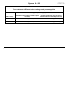
System A -100 doepfer Fuse values for different mains voltages and power supplies Type of power supply 2 Mains voltage A-100NT12 (standard power supply, 650 mA output current) A-100PSU2 (power supply with ring core/toroid transformer and 1.
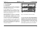
doepfer 2. Overall design System A - 100 2. Overall design 2.1 Introduction The A-100 modular system is based on a standard 19” rack system A-100 G into which individual Modules can be fitted in any chosen layout. The rack system (see Fig. 1) conforms to the 19” standard, and consists of two sections each 3U high, tied together by 6U side panels. It contains two system busses (1), the internal power supply (2) , and the main electrical supply socket (3). Module front panels are all 3U high.
2. Overall design System A - 100 H 2.2 Installing modules A Ignoring this warning can result in damage to your system, and will void your guarantee! Important: Once you’ve checked that there is sufficient current in reserve for the extra module/s, there’s nothing to stop you going ahead and installing them. Read on! Before you install a module into the rack system: D First of all, take the A-100’s plug out of the wall socket.
doepfer 2. Overall design System A - 100 Bus Board Fig. 2: Connecting the ribbon cable to the module D Now join the free end of the ribbon cable (see 2 in Fig. 3) to the nearest available position on the system bus board (see 1 in Fig. 3). A Check very carefully that it is connected so that the coloured marking on the ribbon cable is at the bottom of the bus connector (see 3 in Fig. 3), and it is pushed fully home, not at a slight angle.
2. Overall design System A - 100 A-110 In this case, double-check the connections, making completely sure that the ribbon cable is the right way round where it connects to the module and the bus.
doepfer System A - 100 3. Signal flow in the A-100 Input 3. A-100 signal flow Low Pass Filt er f c VCO Output Pit ch Output 3.1 The Principles of Voltage Control What makes analogue synthesizers (and modular systems in particular) special is that the important parameters of the sound sources (VCO, noise, etc.) and modifiers (VCF, VCA, etc.) can be altered not just by hand, but by voltage control.
3. A-100 signal flow System A - 100 doepfer As well as modules which can be affected by voltage control, there are other modules like the ADSR and LFO which themselves produce voltages to control other modules. 3.2 Signals in the A-100 Usually, these modules need a Trigger Signal to bring them into action. For instance, a GATE Signal, corresponding to a key being pressed on a keyboard, can set off an ADSR, which then puts out its variable voltage “envelope” to affect other modules (see Fig. 6).
doepfer System A - 100 Trigger or Gate Signals, which start a process or function, are typically from 0 V to +5V or 0V to +12 V, with the trigger occurring as the leading edge of the waveform shoots up from 0 V to +5V/12 V. The A-100 modules usually output +12V, but the corresponding inputs of A-100 modules (e.g. Gate, Clock, Reset) will also work with lower levels (typ. +5V).
3. A-100 signal flow System A - 100 doepfer If on the other hand you’d like to have the same internal CV and gate available on two busses at once, you need to link the two together, with the special CV/gate leads, the A-100 BC. This is how you go about it: D Remove the A-100 from the electrical supply. D Remove Jumpers J1 and J2(see p.9) from the upper (see Fig. 8 !) and lower (see Fig. 8 ") system bus boards. ➀ ➁ D Replace the jumpers with the special CV / gate leads, A-100 BC (see Fig. 8 1, 2).
doepfer System A - 100 3.4 Integrating the A-100 with MIDI To link the A-100 into a MIDI system, you can use external MIDI interfaces like our MCV4, MSY2 or MCV24. The MIDI-CV/SYNC Interface A-190-1 is a MIDI-toCV/Gate/Sync interface with the following outputs: • CV 1 (for pitch control, 12 Bit) • CV 2 (any MIDI-Controller, 8 Bit) • Gate • Clock • Start / Stop The A-190 automatically sends pitch control CV and gate information out on the INT.CV and INT.GATE busses. 3.
3.
doepfer System A - 100 4. A-100 Basic Systems It’s not in the nature of modular systems to have hard and fast rules about which modules should be included. But if you’re just starting out along the modular path, it may be difficult to choose a sensible first set of modules. Accordingly, we’ve designed Basic Systems with all the modules mounted in a rack system, and 30 patch leads thrown in as well.
4.
System A - 100 doepfer Part 5. Accessories Description A-100BUS Separate system bus One bus board with 14 connectors for connecting modules, 3 control LEDs (+12,-12,+5V) A-100AD5 5V Low cost adapter Additional power supply producing +5 V / 100 mA; can be connected to any free socket on the system bus board. For modules which require 5V (eg. A-113, 190, 191). This is a cheaper alternative to the NT5 +5 V power supply.
5. Accessories Part A-100OPM A-100SM 16 System A - 100 doepfer Description A-100 User Manual Contains detailed description and instructions for use of all the currently available modules. It is included when you buy a complete system (A-100BS1, BS2, MS). When buying individual modules or frames, you have to order the manual separately. If you order the manual in advance the price for the manual will be credited when ordering a complete system later (not only a single module).
doepfer System A - 100 6. Standard items included 6. Items included as standard A-100G3/G6 - Rack System 3HU/6HU The following parts are included in each order: • Rack system, completely assembled, including two system bus boards, one 12V, 650mA power supply, internal power cables. A-100BS1/BS2/MS - Basic Systems • Rack system (basic frame), completely assembled, including two system bus boards, one 12V, 650mA power supply, internal power cables. • External power lead.
6.
doepfer System A - 100 7. Further reading The resources in the following list should help you increase your knowledge of analog synthesis, and the skill with which you can use modular systems like the A-100. Specialist books In English 7. Further reading Synthesizer Technique ISBN 0-88188-715-3 and Synthesizer Basics ISBN 0-88188-714-5 - (revised re-prints of very useful and authoritative articles from Keyboard magazine, by Moog, Rhea, Milano, Coster, Duke, Powell, Gleeson, DeFuria, Anderton, et al.
7. Further reading System A - 100 doepfer Specialist books in German Elrad, Heise-Verlag Hannover Dellmann / Thewes, Synthesizer-Handbuch, Musik Media / Augsburger Druck- und Verlagshaus, 1985 Electronic Musician, Polyphony Publishing Co., Oklahoma City / USA Enders, Die Klangwelt des Musiksynthesizers, Franzis-Verlag München, 1985, ISBN 3-7723-7761-0 Electronics and Music Maker / Music Technology, Cambridge, England.
8. Module Overview System A-100 The following table may be used for planning and arranging an A-100 system regarding to need of space and current. 8.
System A-100 DOEPFER Module Width Curr. Curr.@5V A-108 12 40 - A-109 20 40 - A-110 10 70 - A-111-1 14 40 - A-111-5 26 80 - A-112 50 - A-113 26 30 100 A-114 4 40 - A-115 8 20 - A-116 8 20 - A-117 8 20 - A-118 A-119 A-120 22 10 8 8 8 20 30 30 - 8.
8. Module Overview System A-100 Module Width Curr. Curr.
System A-100 DOEPFER Module Width Curr.
8. Module Overview Module A-138 a/b/c A-138d A-138e Width Curr. 8 10/20c 8 16 20 10 System A-100 Curr.
System A-100 DOEPFER Module Width Curr. A-144 8 30 A-145 A-146 A-147 8 8 30 20 40 Curr.
8. Module Overview Module Width Curr. A-160 4 40 A-161 A-162 A-163 A-164-1 4 8 8 6 20 40 40 10 System A-100 Curr.
System A-100 DOEPFER Module Width Curr. A-175 4 20 28 Curr.@5V Description Dual Voltage Inverter - two independent analog voltage inverter with displays A-176 8 20 - A-177-1 8 30 - A-177-4 4 ~ 20 8.
8. Module Overview System A-100 Module Width Curr. A-186 4 0 A-187-1 ? ? A-188-1 14 80 - A-188-2 30 120 - A-189-1 8 60 Curr.
System A-100 DOEPFER Module Width Curr. A-196 8 40 A-197-1 14 50 - A-197-2 34 100 - A-198 8 40 - A-199 30 10 80 8. Module Overview Curr.
8.
DOEPFER 32 System A-100 8.
doepfer System A - 100 9.1 Adding a 5V power supply Some A-100 modules, for instance the A-113, A-190 or A-191, need an extra 5 V power supply, as well as the standard one. You can provide this with the A-100 NT5 5 V supply (or in certain circumstances, you can use the 100 AD5 5 V adaptor - see 9.2).
9. Appendix t o t he connect ors of t he bus board System A - 100 doepfer GND (black ) blue blue +5 V (re d) black black or brown blue blue Fig.
doepfer A System A - 100 9. Appendix The yellow/green wire is the safety (earth) connection, and must be never replaced by a different colour. ➂ up oben If you’ve been using the AD5 low-cost 5V adaptor, but are now installing an NT5, you must remove the AD5 before commissioning the NT5! ➀ ➁ rotered Markierung mark 9.
9. Appendix System A - 100 The fins of the heat sink should be facing to the right. It’s vital to make certain that the 16-way plug and socket marry exactly, and aren’t displaced up or down a pin, or to the left or right. If they are misaligned, the adaptor and/ or the power supply may be damaged immediately you switch on.
doepfer System A - 100 9.3. Using the mini power supply/ bus 9.3.1. Introduction The A-100 MNT (Mini power supply / bus) is composed of a miniature power supply and system bus, with connectors for four modules. It’s designed to be used with a small set-up of just a few modules, in your own custom-designed case. The idea is that then you can use individual A-100 modules - for instance the filters, the filterbank, ferquency shifter, sampler, MIDI interface, etc.
9. Appendix System A - 100 doepfer 9.3.2. A-100 MNT - Overview ➀ ➁ Controls: In- / Outputs: 1 LED : LED indicator for +12 V supply. 2 LED : LED indicator for -12 V supply. 34 ! BU 1 : Input for external power supply (7 ... 9 V AC) " ST 1 ... ST 4 : Bus output modules.
System A - 100 doepfer 9. Appendix 9.3.3. Controls / indicators " ST 1 ... ST 4 1 LED The sockets labelled " on the diagram on p.2 are where the modules are connected. • 2 LED LEDs 1 and 2 indicate that the power supply is working properly. Once the MNT is connected, both LEDs should come on.
9. Appendix System A - 100 doepfer 3 Busplatine bus board 1 Best ückungsseite components side 3 Fig. 2: 2 Connecting the ribbon cable to the bus board. D Now fix the module solidly in its case. 1 Fig. 1: 2 Connecting the ribbon cable to the module D Now join the free end of the ribbon cable (see 2 in Fig. 2) to the nearest available position on the system bus board (see 1 in Fig. 2).