
Manual


doepfer
System A - 100 2. Overall design
3
2. Overall design
2.1 Introduction
The A-100 modular system is based on a standard 19”
rack system A-100 G into which individual Modules
can be fitted in any chosen layout.
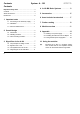
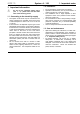
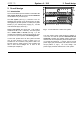
The rack system (see Fig. 1) conforms to the 19”
standard, and consists of two sections each 3U high,
tied together by 6U side panels. It contains two system
busses (
1
), the internal power supply (
2
) , and the
main electrical supply socket (
3
).
Module front panels are all 3U high. Their width is
measured in HP (1 HP = 5.08 mm). The rack system
has a usable width of 84 HP (see Fig. 1). If the
modules you install don’t use up the entire 84 HP, then
you must cover up the spaces with blanking panels.
In each rack system there are two system bus bars
(one for each section), to each of which up to 14
modules can be connected, using ribbon cable. The
bus bar serves to supply power to the modules, and
also to send control voltages etc. to some of the
modules (see Chapter 3).
Fig. 1: A look inside the A-100 G rack system
The rack system power supply produces voltages of
+12 V and -12 V and can put out a maximum current
of 650 mA. In setting up a modular system, make sure
that the total current required by all the modules does-
n’t exceed this maximum. If it does, then a second
power supply (see Accessories) will need to be instal-
led (at position
4,
Fig.1). As a rule, though, one
power supply should be sufficient for a rack system.
4
2
3 HU
84 HP
1
1
3