
Manual
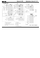


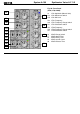
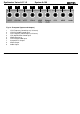


Synthesizer Voice A-111-5 System A-100 DOEPFER
4
Remarks:
• As the LFO frequencies can go up to moderate audio
range (~ 5kHz) even audio FM effects of VCO (pitch
and pulsewidth), VCF and ADSR are possible !
• If the VCO is turned off (waveform switch = center
position, pulsewidth control = fully CCW) and the VCF
resonance is set to maximum the module can be used
as a sine oscillator. The sine can be modulated in a
linear manner from the triangle wave of the VCO and
by LFO2 in an exponential manner at the same time !
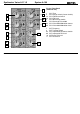
• from the factory the socket labelled "LFO1" outputs the
inverted LFO1 signal. But as the module has several
internal pin headers available even another signal may
appear at this socket by changing the internal module
patch. These six pin headers are available: LFO1
output, LFO2 output, ADSR output, inverter input,
inverter output, output socket. The internal default
patch is LFO1 -> inverter input, inverter output ->
output socket (i.e. socket = inverted LFO1). But even
another signal can be patched to this socket (e.g.
inverted ADSR, non-inverted LFO1, inverted or non-
inverted LFO2). It is also possible to add a blind panel
next to the A-111-5 with a couple of sockets that are
connected to the corresponding pins of the A-111-5 pc
board. The in- and outputs of the VCO, VCF and VCA
are not available as pin headers because the VCO,
VCF and VCA are internally connected in the circuit
which is used in this module.
Additional specifications:
• Front panel width: 24 HP / 121.6 mm
• Module depth: 40 mm (measured from the rear side of
the front panel)
• Current: 80 mA