
Instruction Manual


doepfer
System A - 100
Dual Ring Modulator A-114
3
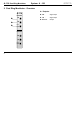
3. In / Outputs
! X In • " Y In
Sockets
!
and
"
are the
signal inputs for the
A-114.
Patch the signals you would like to ring modulate into
these sockets.
The inputs need to have AC signals - so you should
use audio signals, not control voltages. For control
voltages, use a VCA.
§ X*Y Out
Socket
§
is the ring modulator Output.
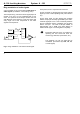
4. User examples
Basic ring modulation
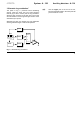
Fig. 1 shows a basic form of ring modulation using two
sine waves. This patch can provide bell- and vibes -
like sounds.
Fig. 1: Ring modulation with two sine waves
X IN
A-114
Y IN
X • Y OUT
RING MO D.
f = 440 Hz
f = 77.7 Hz
f + f = 517.7 Hz
f + f = 362.3 Hz
C
M
C
C
M
M
f
C
- f
M
= 362.3 Hz