
Manual


A-118
NOISE / RANDOM
System A - 100
doepfer
4
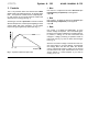
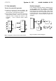
Fig. 2: Random voltage with Rate = 0
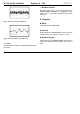
Fig. 3: Random voltage with Rate = 10
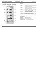
4 Level
The amplitude of the signal at output
§
is adjusted with
this control.
5 Random Control
Use these two LEDs to keep track of whether the
random voltage is positive (+) or negative (-) at any
point in time. Their relative brightness also shows
amplitude.
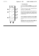
4. Outputs
! White
Output ! produces white noise.
" Colored
Output " produces coloured noise, whose spectrum
is determined by the position of controls
1
and
2
.
§ Random Output
Output § produces a random voltage, whose rate of
change and amplitude are determined by controls
3
and 4.
T