
Instruction Manual
A-121
VCF 2
System A - 100
doepfer
4
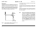
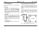
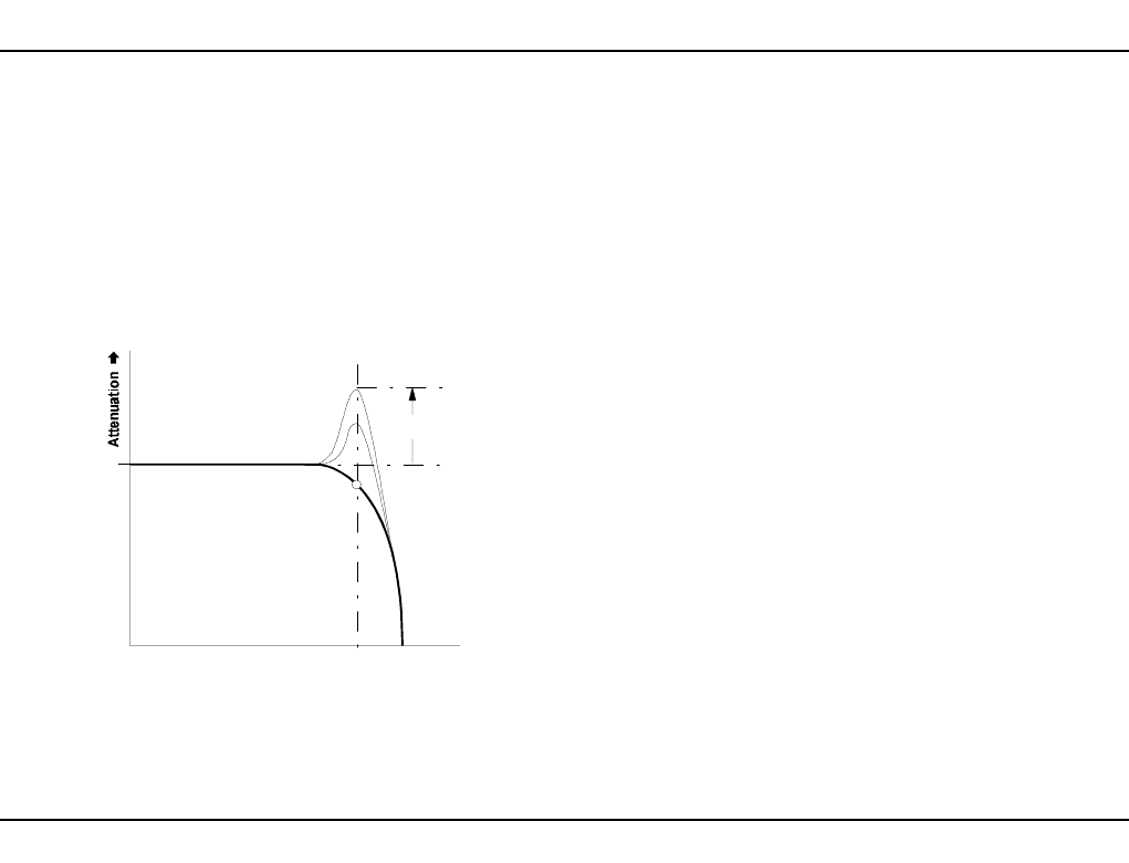
Resonance
Another filter parameter is resonance, also known as
emphasis or Q. As the value for Q gets higher, the
frequencies around the cut-off frequency f
C
are em-
phasised. Fig. 2 shows this process using a low-pass
filter as an example (a high-pass filter would produce a
mirror-image). This way, you can make the frequen-
cies around the cut-off point stand out more.
Fig. 2: How resonance affects the response of a
filter around the cut-off frequency.
In band-pass mode, an increase in Q’s value makes
the bandwidth narrower.
The same is true of notch mode, but of course in this
case this narrower band will be rejected, instead of let
through.
Setting the resonance close to maximum sends the
filter into self oscillation, and makes it behave like a
sine wave oscillator.
H
The A-121’s resonance is not frequency de-
pendent to any significant degree. As long as
resonance is kept below the self-oscillation
level, any variation is imperceptible.
The one exception to this is at high levels of
resonance, coupled with a high cut-off fre-
quency setting, when an increase in reso-
nance can lead to a small drop in the sine-
wave output’s frequency. This is a characte-
ristic of the CEM 3320 filter IC, and is not
due to a design fault in the A-121’s control
system.
f
c
Resonance
Q
Frequency
➨
➨➨
➨
0 db