
Instruction Manual

A-121
VCF 2
System A - 100
doepfer
6
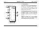
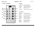
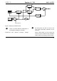
5. In / Outputs
! Audio In
This socket is the filter’s audio input. Patch the
output of a sound source (such as a VCO, noise
generator or mixer) into it.
" FCV 1
Socket FCV 1 is a voltage control input for the filter
frequency. It works to the 1 V / octave standard (like
a VCO).
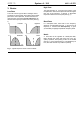
If you patch a modulation source (eg LFO, ADSR) to
this input, the cut-off frequency of the filter will be
modulated by its voltage: ie., the sound color changes
according to the voltage put out by the modulator.
If you use the VCF as a sine wave oscillator, connect
the pitch CV into this socket. Do the same if you want
the filter’s cut-off frequency to track exactly with the
pitch of a note.
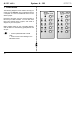
§ FCV 2
Socket FCV 2 is another voltage control input for
the filter. Unlike CV 1, you can control the level of
voltage - the intensity of the modulation effect on the
filter - with attenuator 3.
$ QCV 1
This socket is the voltage control input for the filter’s
resonance. It works to the 1 V / octave standard (like
a VCO).
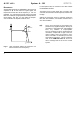
If you patch a modulation source (eg LFO, ADSR) to
this input, the resonance of the filter will be modulated
by its voltage: ie., the sound color of the frequencies
around the cut-off point changes according to the
voltage put out by the modulator.
% QCV 2
This is another voltage control input for controlling
the resonance, but unlike QCV1 it gives you the ability
to use Attenuator 5 to control the amount of voltage
control, and therefore the intensity of its effect on the
filter’s resonance.
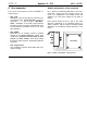
& Notch • / High • ( Band • ) Low
Sockets & to ) are the filter outputs. They simulta-
neously carry the input signal modified by the
respective filter types (see Fig.1).